Supercharge Your Innovation With Domain-Expert AI Agents!

Precision flow feeding device

a feeding device and flow technology, applied in the direction of conveyors, conveyors, transportation and packaging, etc., can solve the problems of inaccurate discharge of quantities and the use of fluidizing gas, and achieve the effect of precise feeding

Active Publication Date: 2022-06-09
REEL ALESA AG
View PDF31 Cites 0 Cited by
  • Summary
  • Abstract
  • Description
  • Claims
  • Application Information

AI Technical Summary

Benefits of technology

The present device allows for the fluidization and potential fluidization of powdery material in a first chamber, followed by its transportation to a second chamber, potential fluidization, transportation to a third chamber, and finally defluidization to produce a stable powdery material in the third chamber. The absence of fluidizing gas prevents turbulences and variations in density, resulting in a precise and steady discharging of the powdery material. The device also includes an intermediate device with fluidizing devices to fluidize and potentially fluidize the powdery material before it reaches the second chamber. The cross-section of the outlet opening of the second chamber can be larger than the discharge element of the third chamber to achieve a steady discharging of small amounts of powdery material per unit of time. The first and second chambers can be located at the same height or different heights, and the third chamber can be located below the second chamber or above it. The design and interaction of the chambers enable precise feeding at various locations.

Problems solved by technology

However, a disadvantage of these devices is that a fluidizing gas has to be used in order to fluidize or potentially fluidize the powdery material, wherein at least part of said fluidizing gas is still present in the powdery material when the latter is to be fed.
This leads to inaccurate quantities being discharged.

Method used


Image

  • Precision flow feeding device
  • Precision flow feeding device
  • Precision flow feeding device

Examples


Embodiment Construction

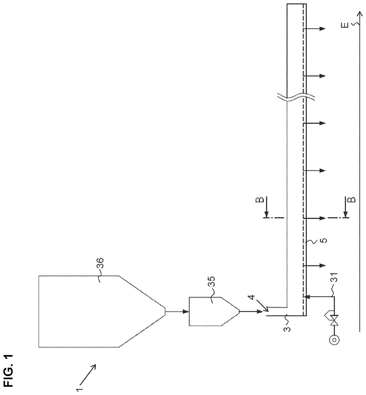
[0049]Different aspects of a device 1 for feeding a processing device (not shown) with powdery material 2 are depicted in FIGS. 1 to 10.

[0050]In particular, said device 1 comprises a first chamber 3 having an elongated shape extending along an extension direction E, and wherein two or more second chambers 6 and two or more third chambers 9 are arranged at a distance from one another along the extension direction E. The following explanations are provided with respect to one second chamber 6 and one third chamber 9 for reasons of simplicity. It should be understood however that these explanations likewise apply to the two or more second chambers 6 and the two or more third chambers 9, respectively.

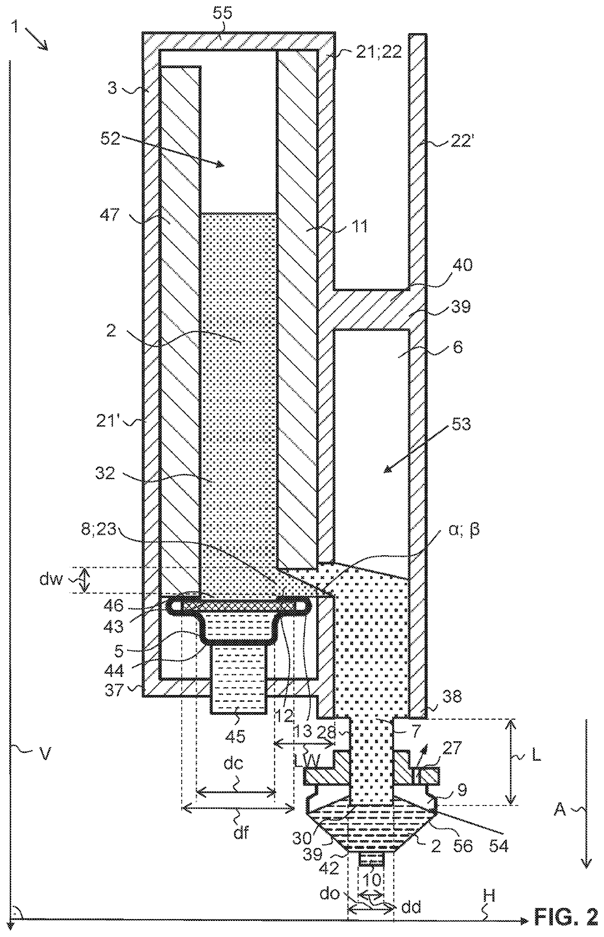
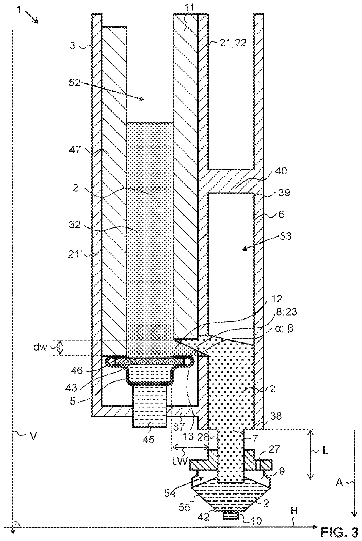
[0051]As best seen in FIGS. 2 to 9, the first chamber 3, the second chamber 6 and the third chamber 9 in each case delimit an interior space 52, 53, 54. In fact, the first chamber 3 comprises side walls 21, 21′ running along a vertical direction V and a bottom wall 37 running along a horizo...


PUM


Abstract

A device (1) for feeding a processing device with powdery material (2) comprises a first chamber (3) having at least one fluidizing device (5) configured to fluidize and / or to potentially fluidize the powdery material (2), at least one second chamber (6) being in connection with the first chamber (3) such that fluidized and / or potentially fluidized powdery material (2) is transportable from the first chamber (3) into the second chamber (6), and at least one third chamber (9) being in connection with the second chamber (6) such, that the potentially fluidized powdery material (2) is transportable from the second chamber (6) into the third chamber (9). The device (1) is configured to defluidize the powdery material (2) such that it is present as defluidized powdery material (2) in the third chamber (9). The third chamber (9) has a discharge element (10) configured to discharge the defluidized powdery material (2).

Description

TECHNICAL FIELD[0001]The present invention relates to a device for feeding a processing device according to claim 1 and a method for feeding a processing device using such a device as claimed in claim 15, respectively.PRIOR ART[0002]Devices for feeding materials are well known in the art. Said devices are subject to many requirements, such as the maintenance of a stable feed or a continuous feed of the powdery material regulated as a function of consumption requirement of the said material. A conveyance of the powdery material in a fluidized or potentially fluidized condition has proven to be advantageous. To this end EP 1 086 035 B1 discloses a device for conveying powdery materials between a storage area and an area to be supplied, wherein the powdery materials are conveyed in a potential fluidization hyperdense bed controlled by a bubble pressure.[0003]Such devices generally deal with aspects regarding mainly the transportation of the material to the feeding area. However, a disa...

Claims


Application Information

Patent Timeline
Patent Type & Authority Applications(United States)
IPC IPC(8): B65G53/20B65G53/60
CPCB65G53/20B65G53/60
Inventor STAUFFER, DAMIANMEIER, PETER
Owner REEL ALESA AG
Features
  • R&D
  • Intellectual Property
  • Life Sciences
  • Materials
  • Tech Scout
  • Unparalleled Data Quality
  • Higher Quality Content
  • 60% Fewer Hallucinations
Learn More