Valve Assembly

a technology of valves and components, applied in the field of valve sub-assembly, can solve the problems of reducing the guiding, tensioning or excess pressure of the resilient friction element, and achieve the effect of less dependent on the operating temperature, more cost-effective and simple assembly

Active Publication Date: 2022-06-09
ROBERT BOSCH GMBH
View PDF9 Cites 1 Cited by
  • Summary
  • Abstract
  • Description
  • Claims
  • Application Information

AI Technical Summary

Benefits of technology

[0008]The valve subassembly having the features of the independent patent claim 1 has the advantage that oscillations of the closure member as a result of a defined axial and radial guiding of the closure element can be prevented or at least reduced. In addition, the functionality can be maintained over the service-life of the vehicle. Furthermore, embodiments of the valve subassembly according to the invention are more cost-effective and simpler to assemble and less dependent on the operating temperature.

Problems solved by technology

This may lead to a decrease of the guiding or the tensioning or excess pressure of the resilient friction element.

Method used


Image

  • Valve Assembly
  • Valve Assembly
  • Valve Assembly

Examples


Embodiment Construction

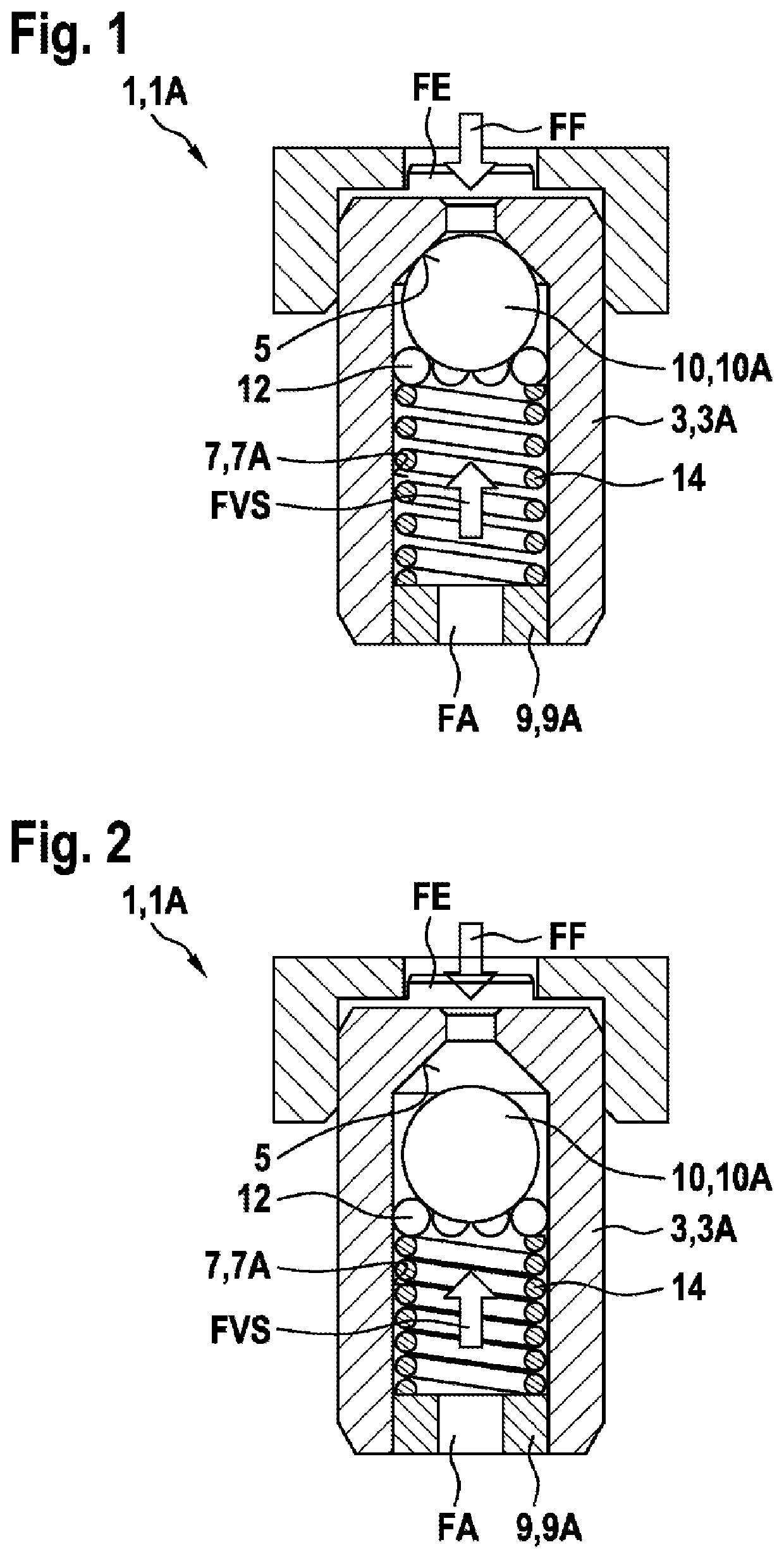
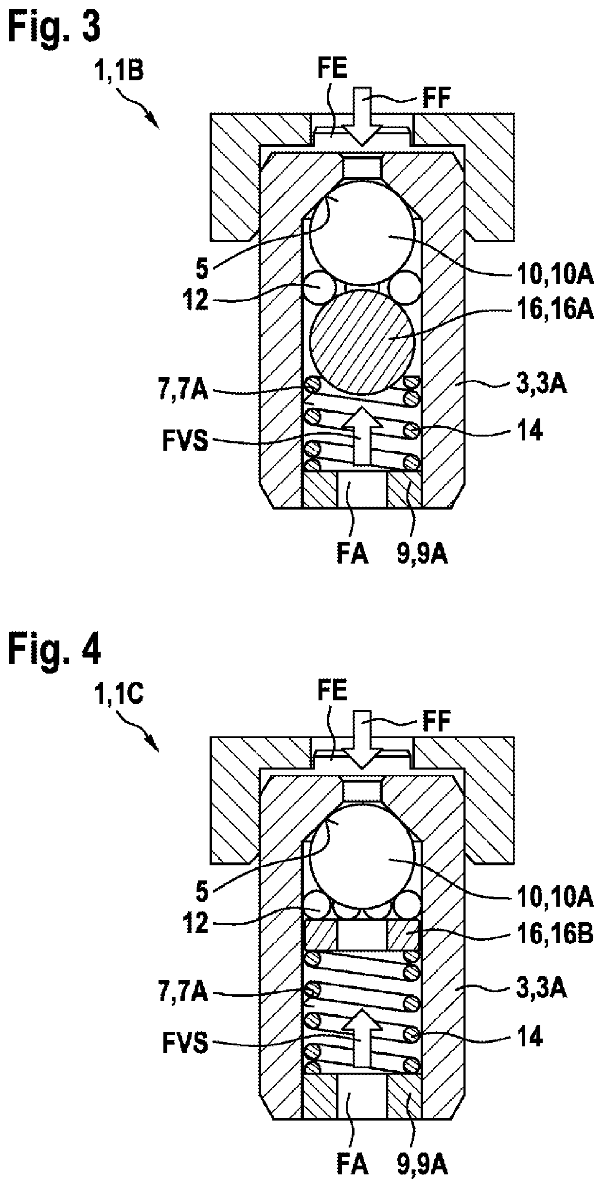
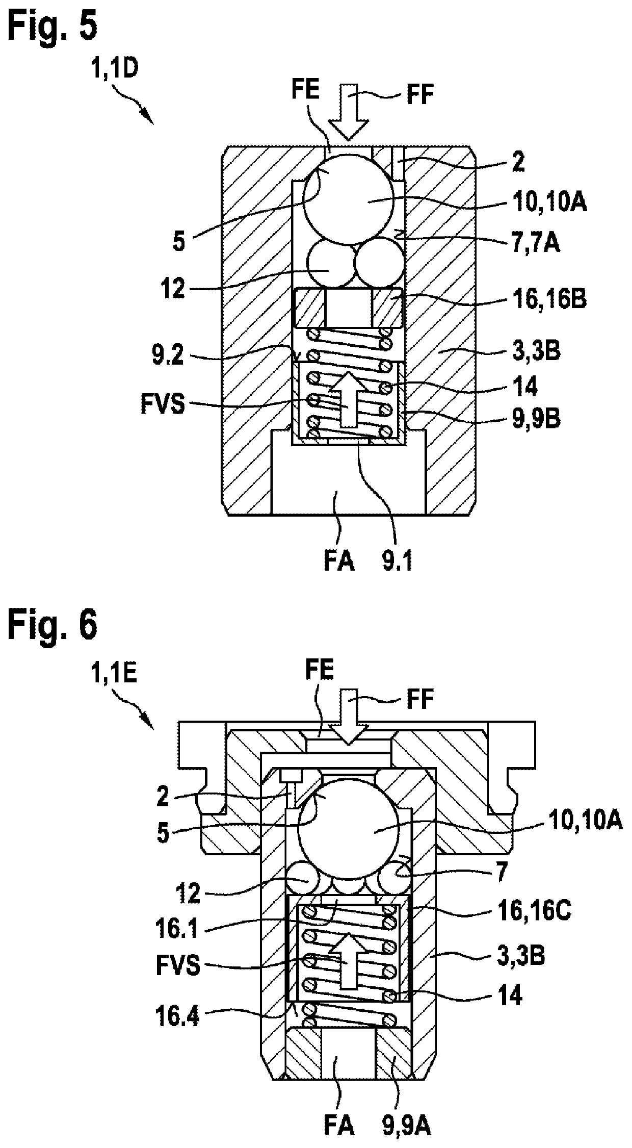
[0039]As can be seen in FIGS. 1 to 9, the illustrated embodiments of a valve subassembly 1 according to the invention in each case comprise a valve member 3, 3A, 3B, 3C, in which a fluid channel 7 which connects a fluid inlet FE to a fluid outlet FA is constructed. A closure member 10 which is movably supported in the fluid channel 7 is acted on in the direction of a valve seat 5 which is constructed in the valve member 3, 3A, 3B, 3C with a pretensioning force FVS, wherein in order to open the valve seat 5 a fluid force FF acts counter to the pretensioning force FVS on the closure member 10. In this instance, the closure member 10 is axially and / or radially guided by means of at least one guiding ball 12. In addition, the at least one guiding ball 12 is arranged between the closure member 10 and a lateral delimitation of the fluid channel 7.

[0040]As can further be seen in FIGS. 1 to 9, the pretensioning force FVS acts via the at least one guiding ball 12 at an angle on the closure m...


PUM


Abstract

The disclosure relates to a valve assembly, comprising a valve body, in which a fluid channel is formed that connects a fluid inlet to a fluid outlet, wherein a preload force is applied to a closing body, which is movably mounted in the fluid channel, in the direction of a valve seat formed in the valve body, a fluid force acting on the closing body against the preload force in order to open the valve seat. The closing body is guided axially and/or radially by at least one guide ball, the guide ball being arranged between the closing body and a lateral boundary of the fluid channel.

Description

[0001]The invention relates to a valve subassembly in accordance with the type of the independent patent claim 1.[0002]Known vehicle braking systems having ABS and / or ESP functionality provide additional functions which support the driver, for example, in maintaining distance from the vehicle in front. This occurs as a result of an active engagement of the additional function in the vehicle braking system by pressure being built up on wheel brake calipers without the driver having activated the brake pedal himself. So that the driver does not hear any disruptive noises, hydraulic damping measures which reduce pressure pulses from a conveyor unit of the vehicle braking system are used. The damping measures may be composed of a hydraulic resistance and a capacitance. For the effectiveness of such a hydraulic damper, a significant throttling by means of a hydraulic resistance is used. It may be considered to be disadvantageous in this instance that, with the significant hydraulic resis...

Claims


Application Information

Patent Timeline
Patent Type & Authority Applications(United States)
IPC IPC(8): F16K17/04
CPCF16K17/0433F16K17/105F16K17/0406B60T15/02F16K15/044F16K15/046F16L55/033F16K15/026B60Y2400/81Y10T137/7927F16K15/042
Inventor LECHLER, ANDREASSTAHR, WOLFSCHELLNEGGER, PATRICKKREUTZER, JOERNEISELE, CHRISTOPHGARDT, ANDREJBIEHLER, MARCUSKLOSS, MICHAELSCHORN, FELIX
Owner ROBERT BOSCH GMBH
Why Eureka
Try Eureka