
Brush for a commutator and commutator motor having the brush

a technology of commutator motor and brush, which is applied in the manufacture of brushes, current collectors, dynamo-electric machines, etc., can solve the problems that the functionality of the electric motor that is also described as a commutator motor cannot be guaranteed, and achieves the effects of reducing production costs, reducing production costs, and reducing production costs

Active Publication Date: 2018-04-24
BROSE FAHRZEUGTEILE GMBH & CO KG HALLSTADT (DE)
View PDF34 Cites 0 Cited by
  • Summary
  • Abstract
  • Description
  • Claims
  • Application Information

AI Technical Summary

Benefits of technology

The invention provides a durable and abrasion-resistant brush for a commutator motor that is simple and cost-effective to assemble and produce.

Problems solved by technology

If the delimiting surfaces were uneven, the brushes could become wedged and the functionality of the electric motor that is also described as a commutator motor would no longer be ensured.

Method used


Image

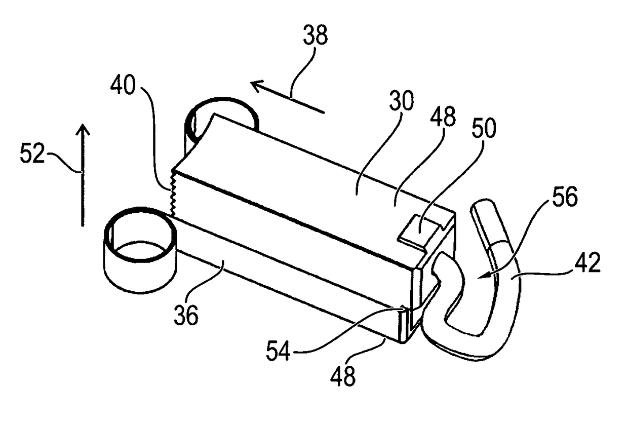
  • Brush for a commutator and commutator motor having the brush
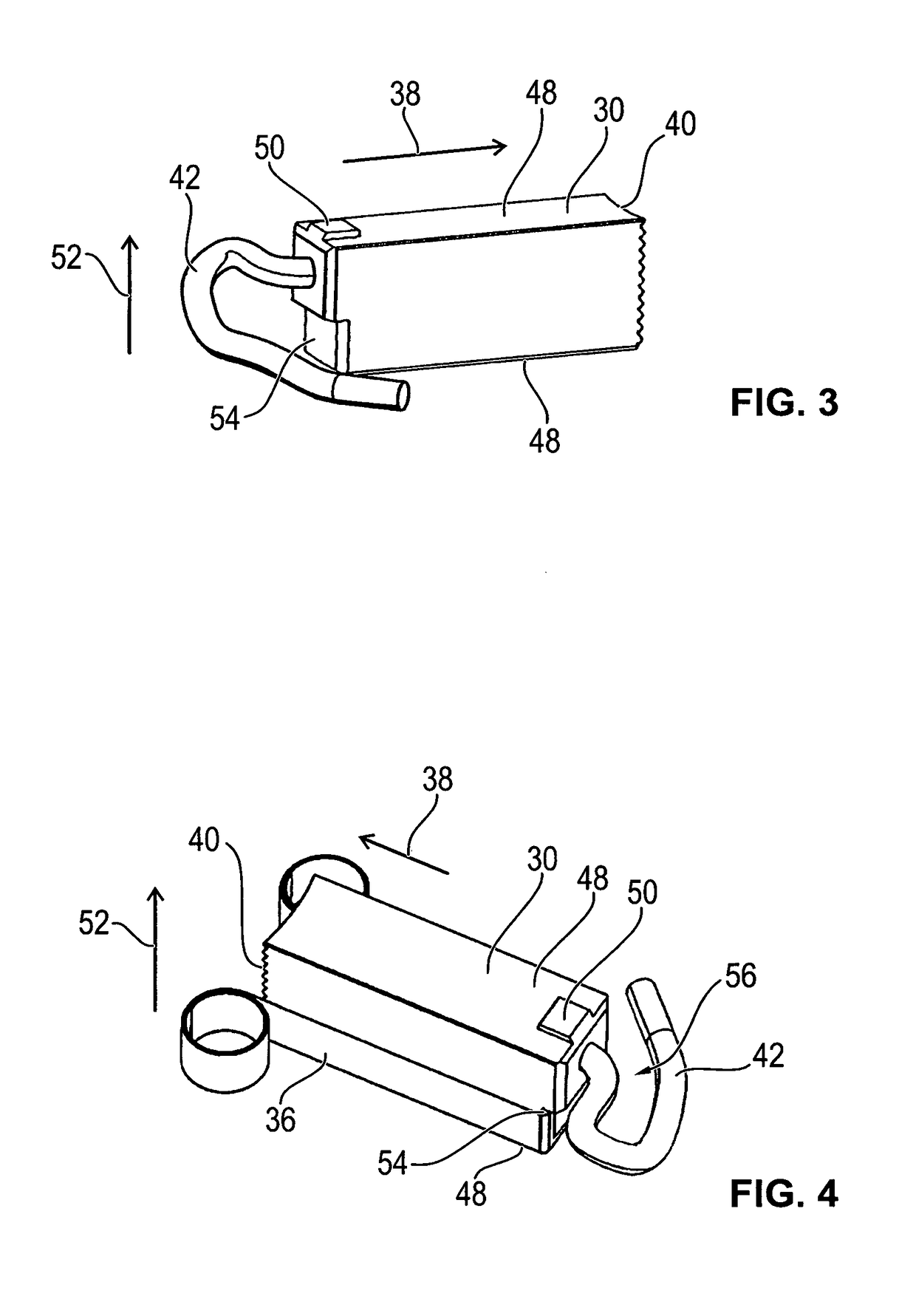
  • Brush for a commutator and commutator motor having the brush
  • Brush for a commutator and commutator motor having the brush

Examples


Embodiment Construction

[0034]Parts that correspond to one another are provided with identical reference numerals in all figures.

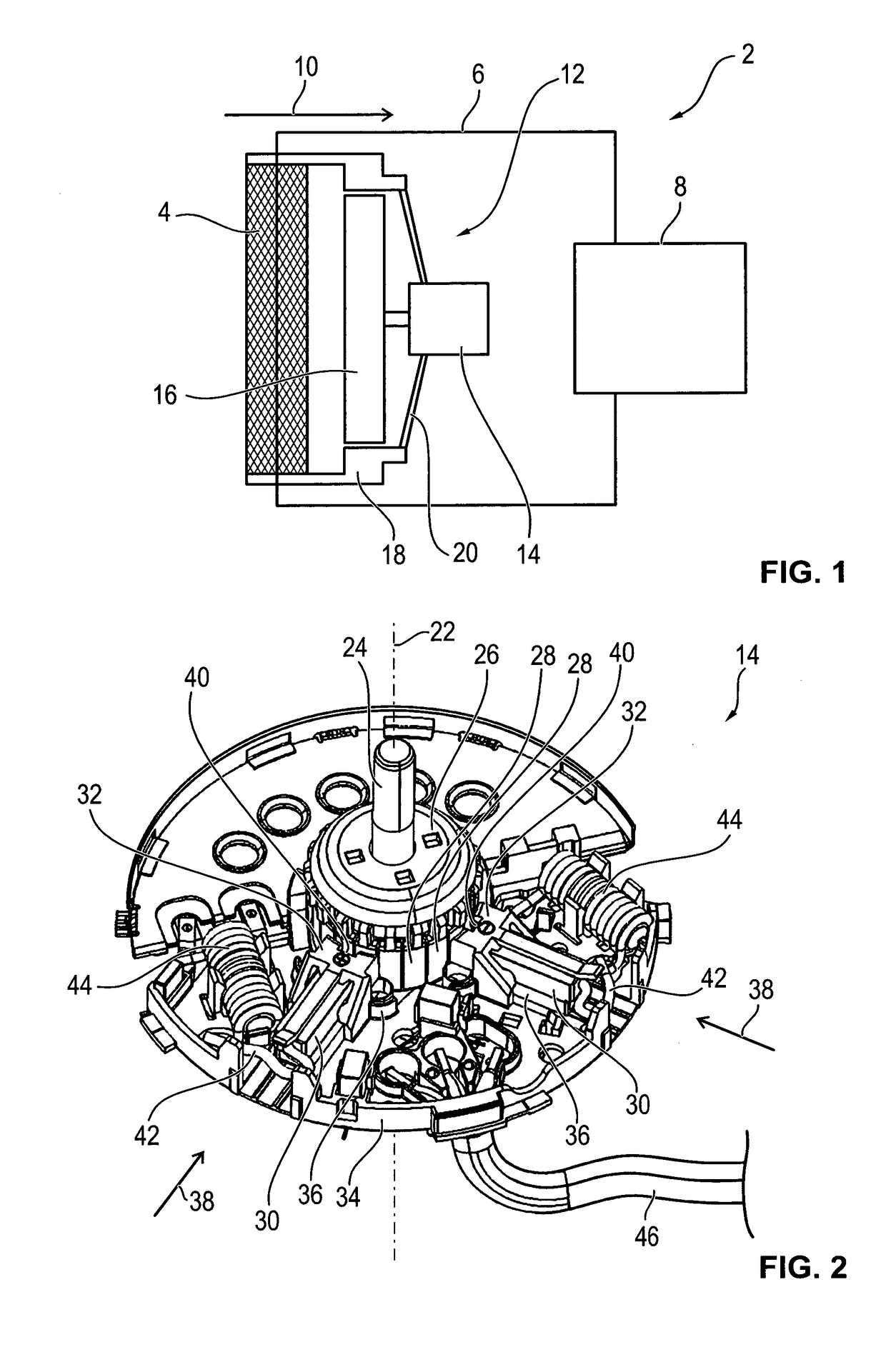
[0035]Referring now to the figures of the drawings in detail and first, particularly to FIG. 1 thereof, there is shown schematically in a simplified manner a side view of a cooling fan 2 of a motor vehicle, in other words a motor vehicle fan. The cooling fan 2 contains a cooling network 4 through which a cooling duct 6 is guided. A cooling fluid is located within the cooling duct 6 and the cooling fluid is kept in circulation by a non-illustrated pump. The cooling fluid is conveyed through an internal combustion machine 8 and is heated by the internal combustion engine, wherein the internal combustion engine 8 is cooled. The heated cooling fluid is then conveyed through the cooling network 4 that is influenced by airflow. The direction of the airflow is along an airflow direction 10 that essentially corresponds to the main direction of travel of the motor vehicle.

[0036]The airflo...


PUM


Abstract

A method produces a brush for a commutator motor, in particularly for a motor vehicle fan, for electrically contacting a connected contact lead to a commutator via a spring-loaded contact with a commutator. Accordingly, a brush material, particularly carbon dust, is poured into a cuboid matrix and compressed by a plunger in a contact direction for forming the brush.

Description

CROSS-REFERENCE TO RELATED APPLICATION[0001]This is a continuation application, under 35 U.S.C. § 120, of copending international application No. PCT / EP2013 / 001455, filed May 16, 2013, which designated the United States; this application also claims the priority, under 35 U.S.C. § 119, of German patent application No. DE 10 2012 010 481.2, filed May 26, 2012; the prior applications are herewith incorporated by reference in their entirety.BACKGROUND OF THE INVENTIONField of the Invention[0002]The invention relates to a brush and a commutator motor having a brush of this type, in particular of a motor vehicle fan.[0003]Motor vehicles having an internal combustion engine generate a considerable amount of heat during operation. In order to maintain the operating temperature of the internal combustion engine and also for the operation of an air conditioning unit, a fluid cooling medium is generally used that in turn must be cooled. This is generally performed by a cooling network that is...

Claims


Application Information

Patent Timeline
Patent Type & Authority Patents(United States)
IPC IPC(8): H01R39/38H01R43/12H01R39/26H02K13/00H01R39/415H01R39/32
CPCH01R39/381H01R39/26H02K13/006H01R43/12H01R39/415H01R39/32
Inventor HEHN, HERMANNPFISTER, MARTINSCHOELE, RAINER
Owner BROSE FAHRZEUGTEILE GMBH & CO KG HALLSTADT (DE)
Learn More