Stabilizer coupling

a technology of stabilizer coupling and coupling plate, which is applied in the direction of interconnection system, mechanical apparatus, and suspensions that are resilient, can solve the problems of reducing the rolling behavior of the vehicle, reducing the torsion stiffness, and causing the stabilizer to twist, etc., and achieves high pressure tightness and durability of the system, simple initial assembly, and high stability.

Inactive Publication Date: 2012-08-02
BENTELER AUTOMOBILTECHNIK GMBH
View PDF11 Cites 0 Cited by
  • Summary
  • Abstract
  • Description
  • Claims
  • Application Information

AI Technical Summary

Benefits of technology

[0024]According to another advantageous embodiment of the present invention, the outer profile element may be coupled with the centerpiece by a screw connection. In this embodiment, a sealing cover may be arranged on the side of the outer profile element facing the centerpiece. With this approach, a particularly cost-effective and simple initial assembly can then be realized, accompanied by high pressure-tightness and durability of the system.
[0025]According to yet another advantageous embodiment of the present invention, the inner profile element may penetrate at least portions of the sealing cover, wherein a flange may be connected to the inner profile element for coupling with a stabilizer section. The stabilizer coupling can then be easily uninstalled from the stabilizer installed in the motor vehicle during subsequent maintenance and repair work. The initial installation and the structure are hereby simplified, while the entire system has a high tightness, even when torque is transmitted over many years.

Problems solved by technology

If one wheel is deflected or rebounds, then this causes the stabilizer to twist.
However, when a more sporty adjustment is selected, the active actuator motor twists the stabilizer more, which then causes a higher torsion stiffness and reduces the rolling behavior of the vehicle in curves traveled in a sporty dynamic fashion.
Disadvantageously, these active stabilizers systems are difficult to manufacture and are technically complex to operate.
In addition, these systems have also a high weight due to the design of the actuators as well as of the sensor system and the control technologies.
A system may also develop technical defects during operation affecting their durability.
Because the stabilizer transmits large torques, these components have a high weight, and are typically manufactured as expensive milled components.

Method used


Image

  • Stabilizer coupling
  • Stabilizer coupling
  • Stabilizer coupling

Examples


Embodiment Construction

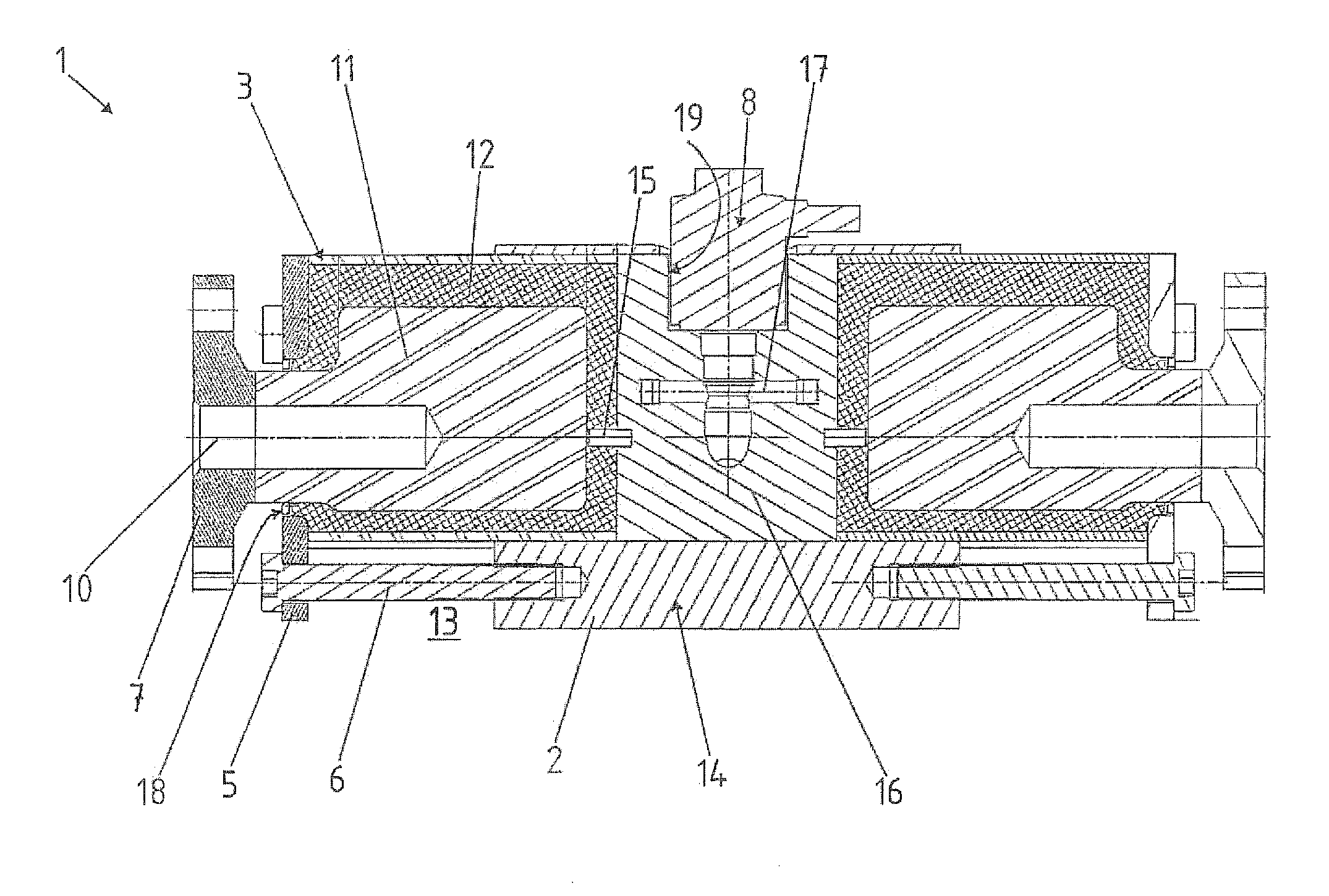
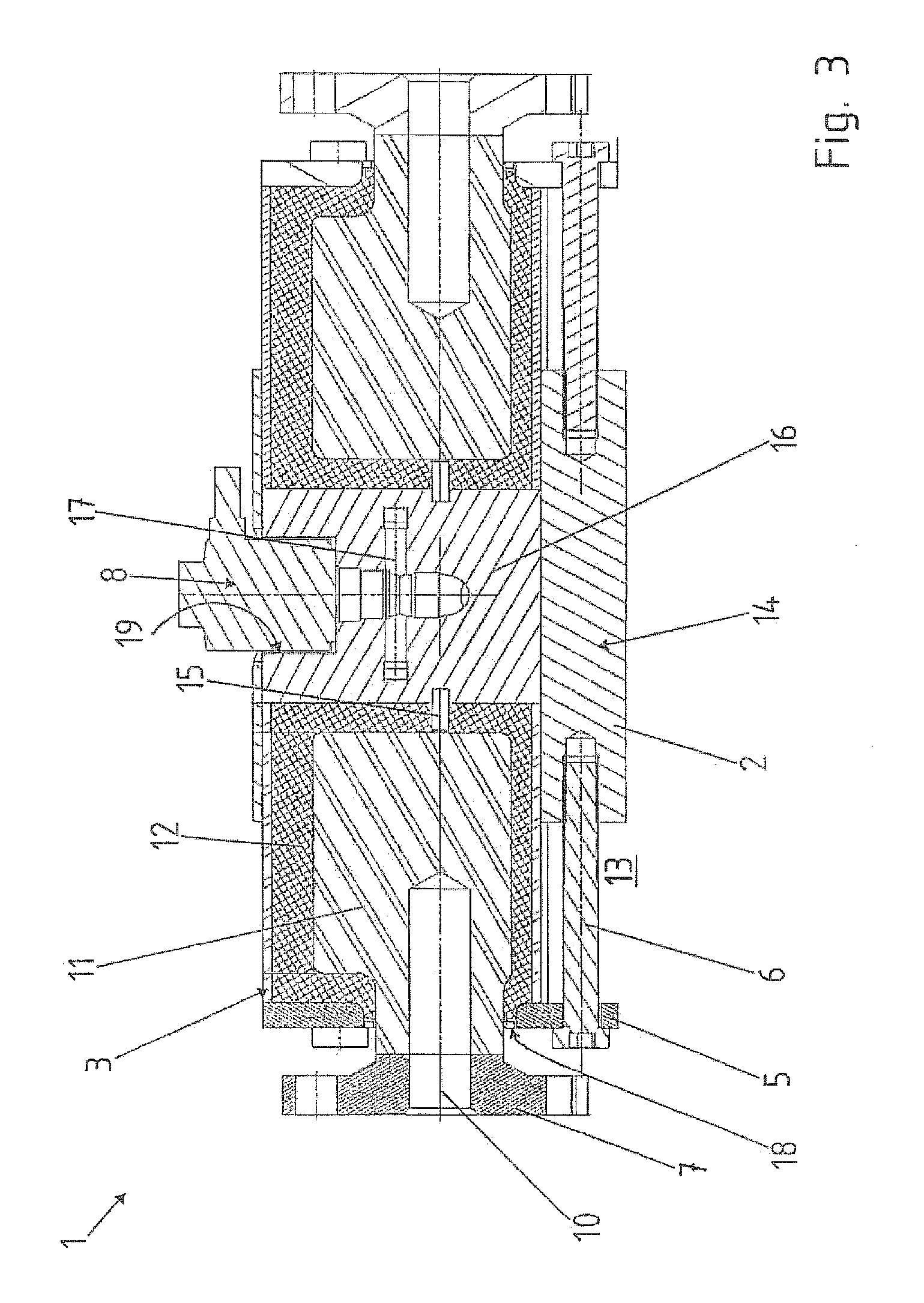
[0030]Throughout all the figures, same or corresponding elements may generally be indicated by same reference numerals. These depicted embodiments are to be understood as illustrative of the invention and not as limiting in any way. It should also be understood that the figures are not necessarily to scale and that the embodiments are sometimes illustrated by graphic symbols, phantom lines, diagrammatic representations and fragmentary views. In certain instances, details which are not necessary for an understanding of the present invention or which render other details difficult to perceive may have been omitted.

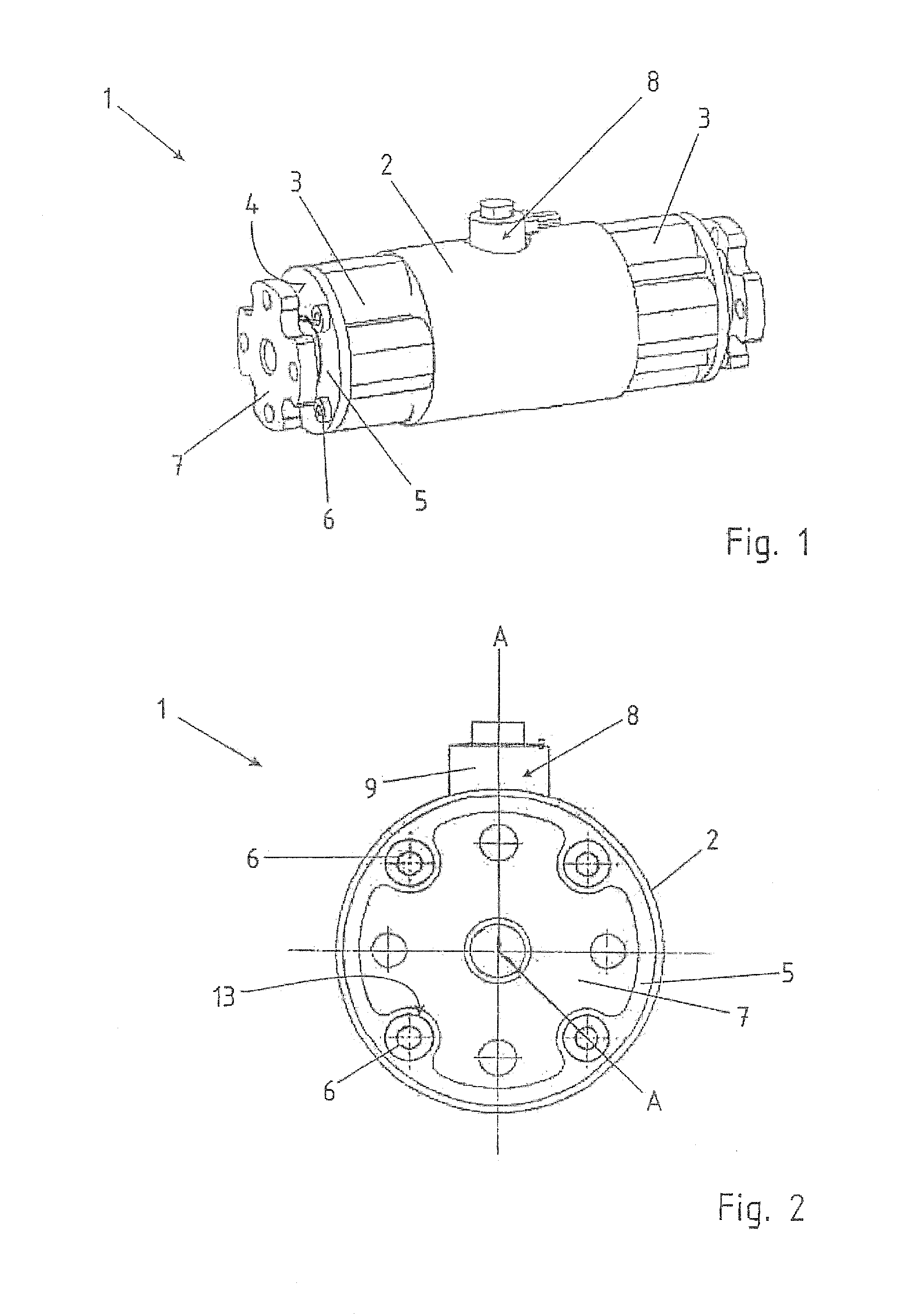
[0031]Turning now to the drawing, and in particular to FIG. 1, there is shown a perspective view of a stabilizer coupling 1. The stabilizer coupling 1 includes a sleeve component 2, from which two outer profile elements 3 extend. The outer profile elements 3 are each screwed to the sleeve component 2 at an end face 4 by way of a sealing cover 5. In addition, a flange 7 is ar...


PUM


Abstract

A stabilizer coupling for use in a roll stabilizer for a motor vehicle has at least one actuator, with the actuator being formed by an outer profile element and an inner profile element. An elastically deformable body is arranged between the outer profile element and the inner profile element. The outer profile element is formed as a hollow profile component, in particular a hollow profile component constructed as an extruded profile and made from a light metal alloy.

Description

CROSS-REFERENCES TO RELATED APPLICATIONS[0001]This application claims the priority of German Patent Application, Serial No. 10 2011 009 738.4, filed Jan. 28, 2011, pursuant to 35 U.S.C. 119(a)-(d), the content of which is incorporated herein by reference in its entirety as if fully set forth herein.BACKGROUND OF THE INVENTION[0002]The present invention relates to a stabilizer coupling for use in a roll stabilizer for a motor vehicle.[0003]The following discussion of related art is provided to assist the reader in understanding the advantages of the invention, and is not to be construed as an admission that this related art is prior art to this invention.[0004]Stabilizers for roll stabilizing of motor vehicles are known in the art. These stabilizers are typically constructed as torsion components. One side of the stabilizer is coupled with the left wheel of the motor vehicle, whereas the other side of the stabilizer is coupled with the right wheel of a motor vehicle axle. If one whee...

Claims


Application Information

Patent Timeline
Patent Type & Authority Applications(United States)
IPC IPC(8): B60G21/055
CPCB60G21/0558B60G11/62B60G11/64F16F15/1245F16F15/162B60G2500/22B60G2204/8304B60G2206/427B60G2206/71B60G2206/8105B60G2500/10B60G2204/82
Inventor SEIBT, OLIVERKROGMEIER, JURGENILLG, IGORBERHEIDE, FRISOJANZEN, ANDREAS
Owner BENTELER AUTOMOBILTECHNIK GMBH
Why Eureka
Try Eureka