
Haptic feedback device provided with stiffeners

a technology of stiffener and feedback device, which is applied in the direction of instrumentation, signalling system, and signalling system, etc., can solve the problems of interference that disrupts the modal deformation, reduces the efficacy of linear actuator array actuation, and has a drawback of the approach

Pending Publication Date: 2022-06-09
HAP2U
View PDF9 Cites 0 Cited by
  • Summary
  • Abstract
  • Description
  • Claims
  • Application Information

AI Technical Summary

Benefits of technology

The patent describes a method for creating a surface with specific vibration properties using stiffening elements distributed over one side of a carrier. These stiffeners create grooves on the surface of the carrier, which allow vibrations to spread faster or slower depending on how they are propagating. The stiffeners also help to minimize the interference between vibrations and produce a unique wave pattern. A thin layer of a material with low viscoelastic losses can be used to cover the surface of the carrier, without affecting its resonance. The technical effects of this method include improved vibration control and reduced interference between vibrations.

Problems solved by technology

However, this approach has a drawback.
However, when for example the (length-to-width) aspect ratio of the surface to be actuated approaches 1, two modes substantially at the same resonant frequency, one directed along the X-axis and the other along the Y-axis, superpose, this creating interference that disrupts the modal deformation.
This effect decreases the efficacy of the actuation by the linear actuator array, because of the incompatibility between the position of the actuators and the waveform of the modal deformation.
Other problems may add to the problems created by interference, such as problems due to focusing of the waves, which cause local over-intensities, and therefore a variability in the amplitude of vibration of the carrier, for example in carriers comprising concavities, and in an extreme case when the carrier is disk-shaped.

Method used


Image

  • Haptic feedback device provided with stiffeners
  • Haptic feedback device provided with stiffeners
  • Haptic feedback device provided with stiffeners

Examples


Embodiment Construction

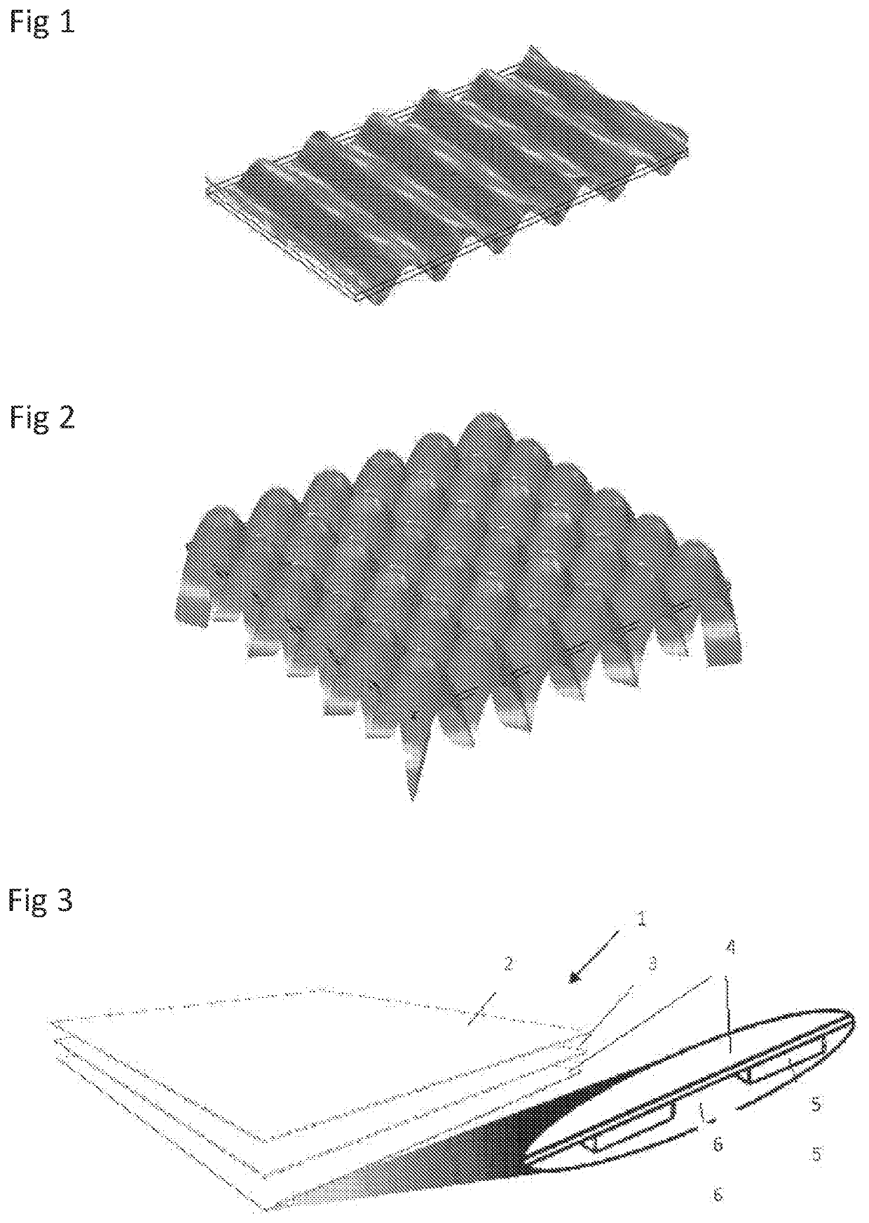
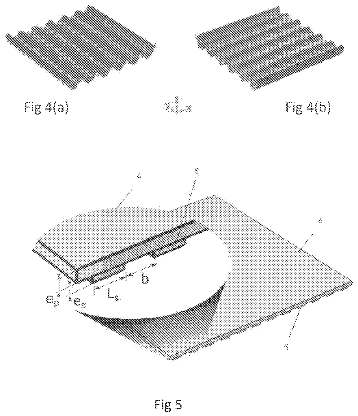
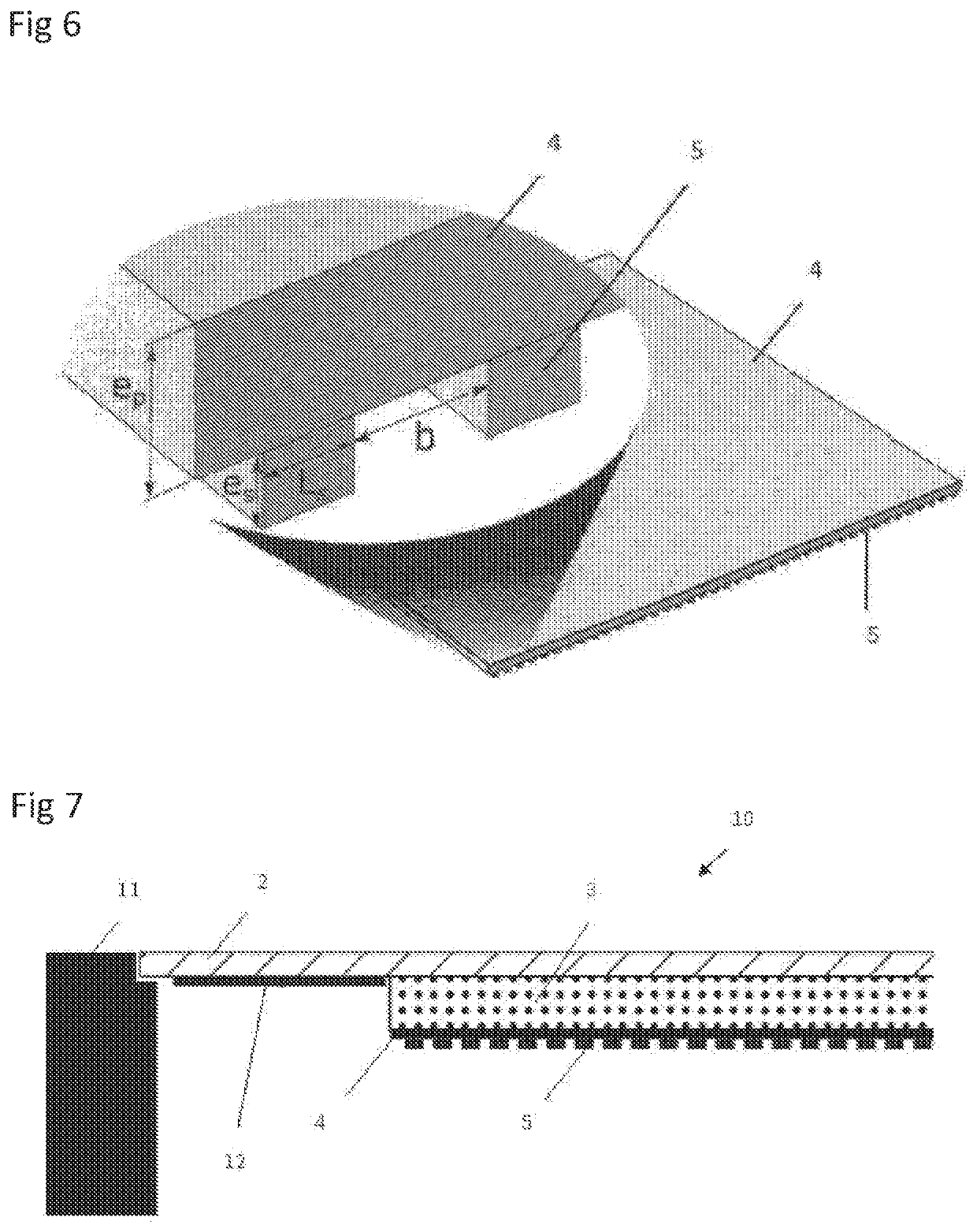
[0028]The invention will be described in more detail with reference to the figures, in which:

[0029]FIG. 1 shows the modal deformation of a rectangular plate made of purely elastic material at a natural frequency;

[0030]FIG. 2 shows, for a square plate made of a purely elastic material, the modal deformation corresponding to the interference between two axial modes in x and y that coexist at the same frequency;

[0031]FIG. 3 shows a perspective view of a first embodiment of the invention;

[0032]FIG. 4 shows the modal deformation of a square plate made of rigid material and provided with stiffeners according to the invention;

[0033]FIG. 5 shows a perspective view of one particular embodiment of the invention, which embodiment is tailored to an ultrasonic vibration frequency of 20 kHz;

[0034]FIG. 6 shows a perspective view of one particular embodiment of the invention, which embodiment is tailored to an ultrasonic vibration frequency of 200 kHz;

[0035]FIG. 7 shows a partial cross-sectional vi...


PUM


Abstract

The invention relates to a haptic feedback device comprising a support which can be vibrated and of which a first face is coated with at least one layer for detecting the position of a user's finger. The device includes electromechanical actuators which are aligned along an edge of the support or the layer and which are capable of making the support and the layer vibrate at an ultrasonic resonance frequency. The support comprises on the second face thereof a set of stiffeners distributed over the whole of said second face and configured to make it more difficult to bend the support along an axis perpendicular to the stiffeners, the stiffeners being designed to produce an axial and uniform vibration mode for the support, all the antinodes of which are of substantially equal amplitude.

Description

FIELD OF THE INVENTION[0001]The invention relates to haptic-feedback surfaces based on the principle of ultrasonic lubrication.PRIOR ART[0002]Haptic-feedback devices in which the propagation medium of the vibrations is a thin vibratable plate are known. A plate is said to be “thin” when it possesses a thickness that is small compared to its two other dimensions and compared to the wavelength of the vibratory waves in question.[0003]As known, the plate may be monolithic or multi-layer and of rectangular shape. Electromechanical actuators are placed on the plate so as to excite an axial vibratory mode, i.e. one the vibrational nodes of which are aligned with respect to one another along a line parallel to one of the edges of the plate.[0004]In a plate the thickness of which is no more than twice the wavelength of the vibration generated by the actuators, flexural waves referred to as A0 Lamb waves (or quasi-Lamb waves in the case of a multilayer plate that is asymmetric in thickness) ...

Claims


Application Information

Patent Timeline
Patent Type & Authority Applications(United States)
IPC IPC(8): G06F3/043G06F3/01H01L27/32G06F3/041H10N30/20
CPCG06F3/043G06F3/0412H01L27/3225G06F3/016G08B6/00H10K59/00
Inventor RUPIN, MATTHIEU
Owner HAP2U
Learn More