
Electroluminescence display

a technology of electroluminescence display and large area, applied in the direction of diodes, semiconductor devices, electrical apparatus, etc., can solve the problems of deteriorating display quality, external light reflected, and difficulty in ensuring the quality of materials capable of providing various color temperature, so as to prevent or mitigate external light reflection

Pending Publication Date: 2022-06-09
LG DISPLAY CO LTD
View PDF0 Cites 0 Cited by
  • Summary
  • Abstract
  • Description
  • Claims
  • Application Information

AI Technical Summary

Benefits of technology

The present invention aims to provide an electroluminescence display that can adjust the color temperature without developing a light emitting element, suppress the reflection of external light without lowering luminance, and prevent or mitigate a decrease in luminance. The display includes a color temperature control layer and a light absorbing element and / or light reflecting layer to achieve these purposes.

Problems solved by technology

It is very difficult to ensure the materials capable of providing various color temperature due to the characteristics of the light emitting device material.
In addition, for the flat panel display device, such as an electroluminescence display, there is a problem in which external light is reflected and display quality is deteriorated.
In order to prevent luminance degradation, higher power may be used, but it causes an increase in power consumption.

Method used


Image

  • Electroluminescence display
  • Electroluminescence display
  • Electroluminescence display

Examples


Embodiment Construction

[0046]Reference will now be made in detail to the exemplary embodiments of the present disclosure, examples of which are illustrated in the accompanying drawings.

[0047]Advantages and features of the present disclosure, and implementation methods thereof will be clarified through following example embodiments described with reference to the accompanying drawings. The present disclosure may, however, be embodied in different forms and should not be construed as limited to the example embodiments set forth herein. Rather, these example embodiments are provided so that this disclosure may be sufficiently thorough and complete to assist those skilled in the art to fully understand the scope of the present disclosure. Further, the protected scope of the present disclosure is defined by claims and their equivalents.

[0048]Wherever possible, the same reference numbers will be used throughout the drawings to refer to the same or like parts. In the specification, it should be noted that like r...


PUM

PropertyMeasurementUnit
angleaaaaaaaaaa
DAaaaaaaaaaa
color temperatureaaaaaaaaaa

Abstract

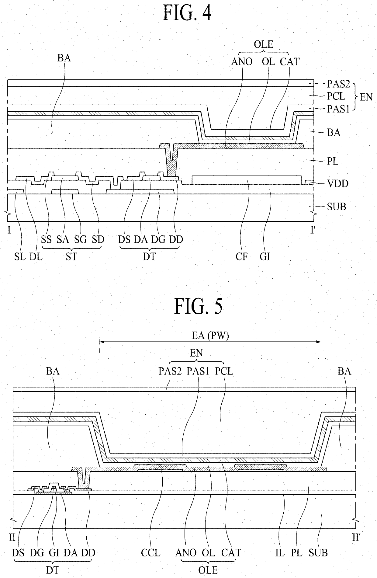
A disclosed electroluminescence display may include: a substrate; a driving element on the substrate; an anode electrode on the substrate and connected to the driving element; a bank on the anode electrode and defining an emission area at the anode electrode; a light emitting layer on the bank and the anode electrode; a cathode electrode on the light emitting layer; and a color temperature control layer between the anode electrode and the substrate in the emission area.

Description

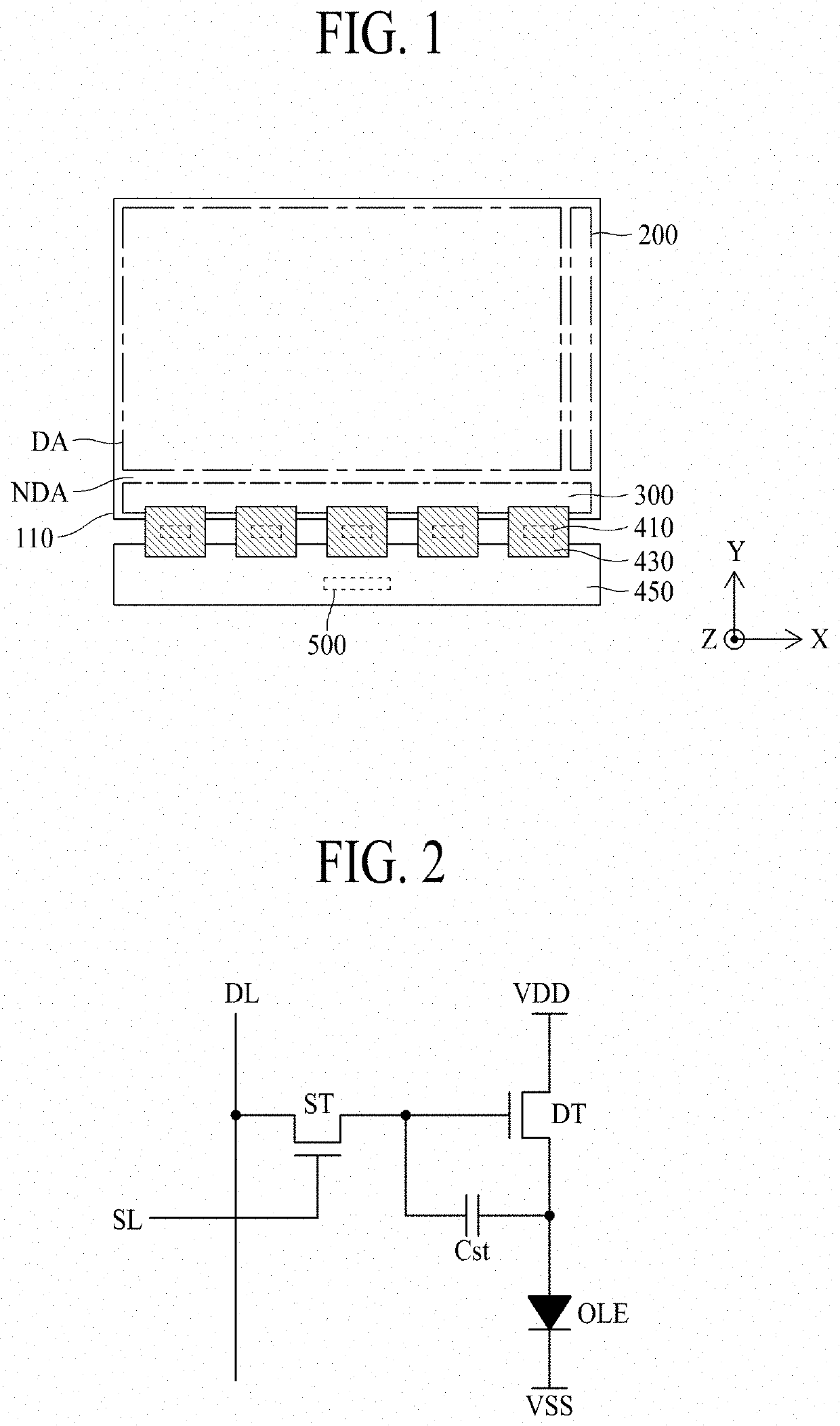
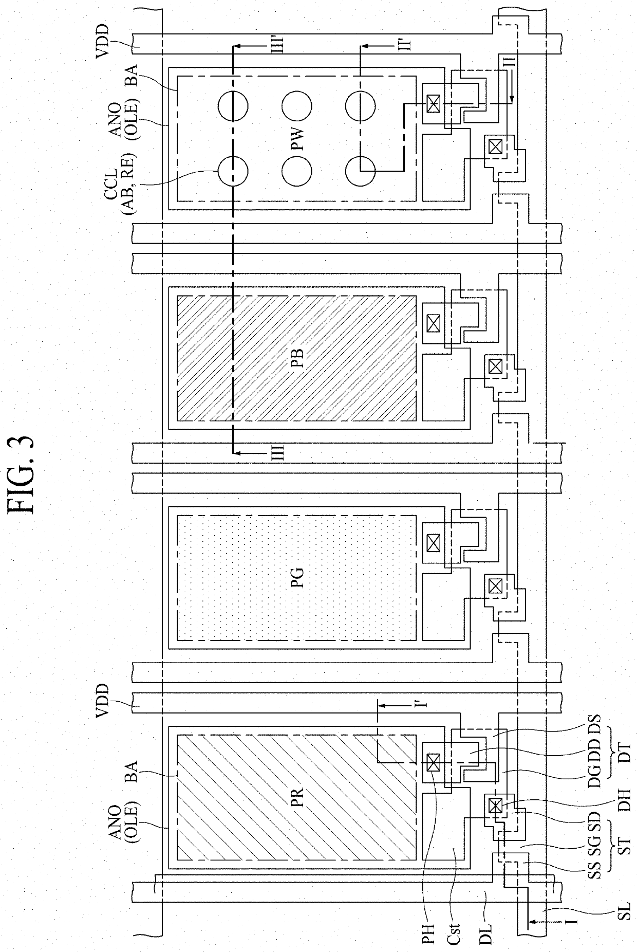
CROSS-REFERENCE TO RELATED APPLICATIONS[0001]This application claims the benefit of and priority to Korean Patent Application No. 10-2020-0170213 filed on Dec. 8, 2020, which is hereby incorporated by reference as if fully set forth herein.BACKGROUND1. Technical Field[0002]The present disclosure relates to a large area electroluminescence display. Especially, the present disclosure relates to an electroluminescence display having a structure in which the color temperature may be easily controlled. Further, the present disclosure relates to an electroluminescence display capable of easily adjusting color temperature and preventing or mitigating external light reflection without a polarizing element.2. Description of the Related Art[0003]Recently, various types of displays, such as cathode ray tubes (CRTs), liquid crystal displays (LCDs), plasma display panels (PDPs) and electroluminescent displays, have been developed. These various types of displays are used to display image data of...

Claims


Application Information

Patent Timeline
Patent Type & Authority Applications(United States)
IPC IPC(8): H01L27/32H01L51/52
CPCH01L27/322H01L51/5284H01L51/5221H01L27/3246H01L51/5271H10K59/38H10K59/80515H10K59/878H10K59/8792H10K59/351H10K59/124H10K59/122H10K50/856H10K50/865H10K50/82
Inventor PARK, TAEHAN
Owner LG DISPLAY CO LTD
Learn More