Orbital floor implant

a technology of floor and implant, which is applied in the direction of prosthesis, internal osteosynthesis, osteosynthesis devices, etc., can solve the problems of difficult shape and trim, difficulty in reconstructed parts, and variety of problems in the eye socket, so as to facilitate tissue ingrowth/stabilization, provide rigidity and malleability, and facilitate the effect of tissue ingrowth/stabilization

Pending Publication Date: 2022-06-30
PORIFEROUS
View PDF0 Cites 2 Cited by
  • Summary
  • Abstract
  • Description
  • Claims
  • Application Information

AI Technical Summary

Benefits of technology

[0006]Embodiments of the present disclosure provide an orbital floor implant. In one embodiment, the implant has a first surface that is a fully porous, bone-side layer. This porous layer/side encourages tissue ingrowth/stabilization, and may provide needed volume to restore the globe to the correct position. The implant has a second surface that is a non-porous, orbital content-side layer. The

Problems solved by technology

In some instances, a variety of problems can occur in the eye socket, ranging from inflammatory diseases or other diseases, tumors, infections, birth defects, or injuries from trauma.
When these problems occur, it may become necessary to reconstruct various portions of the orbital socket, including the orbital floor.
Additionally problems associated with traditional titanium

Method used


Image

  • Orbital floor implant
  • Orbital floor implant
  • Orbital floor implant

Examples


Embodiment Construction

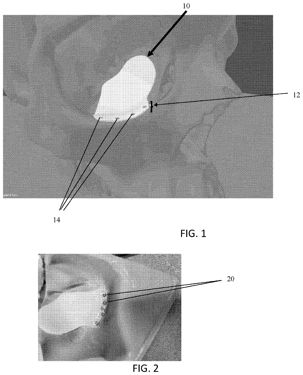
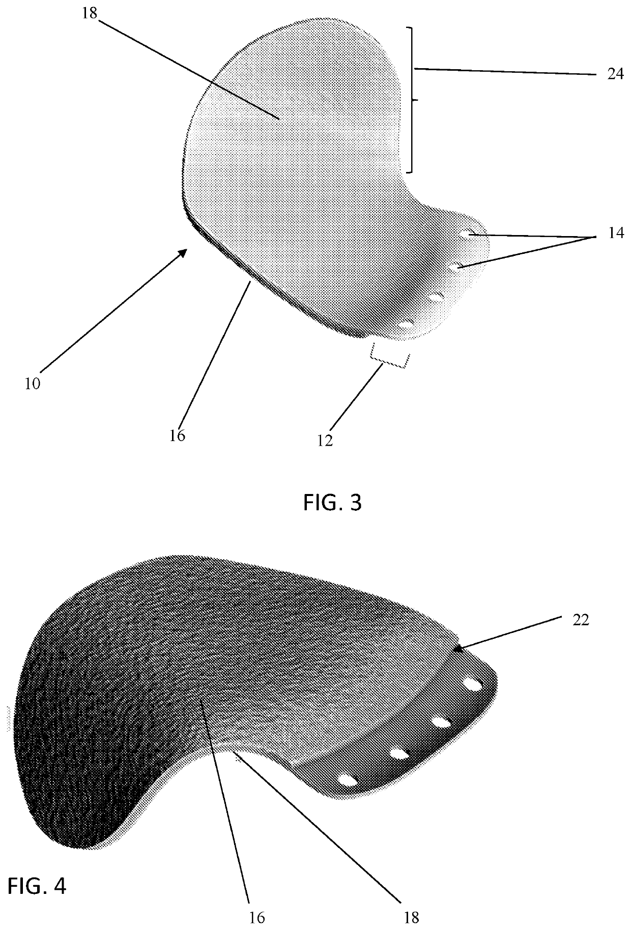
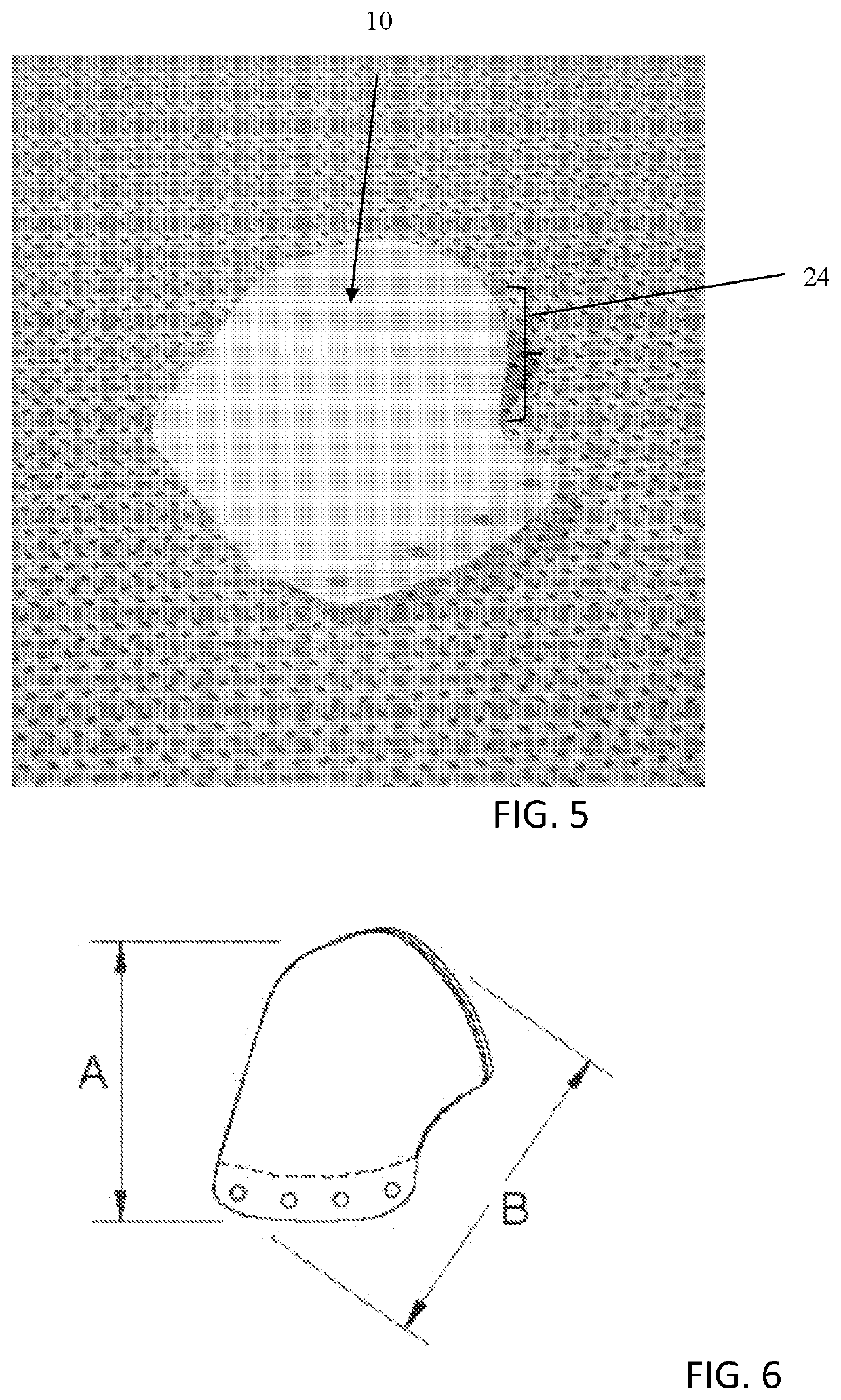
[0019]FIG. 1 illustrates an implant 10 positioned with respect to a patient's orbital bone. An extending tab 12 is secured to the patient's inferior orbital rim in use. The tab 12 may have a plurality of eyelets or openings 14 that allow its securement (via one or more screws) to the patient's bone. Although not shown, the tab 12 may also have additional or multiple rows of eyelets or openings to allow for more inferior screw placement, if desired by the surgeon. The openings 14 are generally sized to receive a screw such that the screw sits flush with respect to the implant / tab surface.

[0020]In a specific example, the implant 10 is made of a polyethylene material, such that the surface of a fixation device 20, such as a screw, can depress slightly into the material, in order for the screw head to remain flush, even if it would otherwise slightly protrude. This is illustrated by FIG. 2. If a surgeon does not choose to use one or more of the openings 14, it is also possible for a scr...


PUM

PropertyMeasurementUnit
Lengthaaaaaaaaaa
Thicknessaaaaaaaaaa
Thicknessaaaaaaaaaa

Abstract

Embodiments of the present disclosure relate generally to an orbital floor implant (10). One embodiment provides an implant with a first surface that is a fully porous, bone-side layer (16) and a second surface that is a non-porous, orbital content-side layer (18). The implant material itself may be polymeric material throughout, without the need for an embedded mesh or other support matrix. The implant is provided in a pre-shaped configuration and is of a material that allows it to be bent for shaping purposes. An extending tab (12) with eyelet portion/opening (14) can enhance securement options to a patient's bone.

Description

[0001]This application claims the benefit of U.S. Provisional Application Ser. No. 62 / 841,969, filed May 2, 2019 titled “Orbital Floor Implant,” the entire contents of which are hereby incorporated by reference.FIELD OF THE DISCLOSURE[0002]Embodiments of the present disclosure relate generally to an orbital floor implant. One embodiment provides an implant with a first surface that is a fully porous, bone-side layer and a second surface that is a non-porous, orbital content-side layer. The implant material itself may be polymeric material throughout, without the need for an embedded mesh or other support matrix. The implant is provided in a pre-shaped configuration and is of a material that allows it to be bent for shaping purposes. An extending tab with eyelet portions can enhance securement options to a patient's bone.BACKGROUND[0003]The orbit is the boney socket in the skull that contains and houses the eye, along with the associated structures that support eye function, such as ...

Claims


Application Information

Patent Timeline
IPC IPC(8): A61F2/28A61B17/80A61B17/86
CPCA61F2/2875A61B17/8061A61B17/8085A61F2002/30578A61B17/86A61F2002/2878A61F2/2846A61B2017/00946A61F2/30734A61F2/30942A61F2002/2889A61F2002/30011A61F2002/3008A61F2002/30133A61F2002/30301A61F2002/30324A61F2002/30576A61F2002/30736A61F2002/30772A61F2002/30784A61F2002/3096A61F2250/0023A61F2250/0024B29K2023/06B29K2023/0683B29K2823/06B29K2823/065B29K2823/0683A61F2002/30971A61F2002/3092A61F2002/3093
Inventor NOBLE, AARON
Owner PORIFEROUS
Why Eureka
Try Eureka