
Three stage membrane gas separation with cooling and use of sweep gas

a membrane gas and sweep gas technology, applied in the direction of membranes, separation processes, domestic cooling apparatus, etc., can solve the problems of undesirable membrane cooling, increased operating costs of such a system, and increased compression

Inactive Publication Date: 2022-06-30
LAIR LIQUIDE SA POUR LETUDE & LEXPLOITATION DES PROCEDES GEORGES CLAUDE
View PDF0 Cites 0 Cited by
  • Summary
  • Abstract
  • Description
  • Claims
  • Application Information

AI Technical Summary

Benefits of technology

The invention is surprising because it was previously thought to have a disadvantageous effect of losing the first gas in the product gas. However, this patent text explains how the invention overcomes this issue and makes the process more efficient.

Problems solved by technology

While this may be a satisfactory solution for some separations, this requires a greater amount of compression and thus increases the operating expense for such a system.
With the exception of gases having very low inversion temperatures, such as hydrogen and helium, the relatively greater amount of Joule-Thomson cooling caused by this greater partial pressure difference can result in undesirable cooling of the membrane and potentially condensation of condensable components of the gas mixture on the feed side of the membrane.
Similar to increasing the feed pressure (as explained above), this may result in an undesirable level of cooling of the membrane and potential condensation of condensable components on the feed side of the membrane.
As a result, the operating expense of such a membrane separation scheme is increased due to the increased need for compression energy for the additional amount of recycle gas.
Therefore, there is a need to increase the flux of a gas through a gas separation membrane without resulting in increased compression costs, excessive membrane cooling, condensation of condensable components of a gas mixture on a membrane, or decreased recovery as has been experienced with conventional gas separation membrane schemes.
Because an ideal separation is characterized by both a high selectivity and a high flux, outside of certain niche applications, manipulating the membrane or feed gas temperature has not shown itself to be a satisfactory way of improving gas separations using gas separation membranes.
While greater amounts of the product gas may be obtained in this manner, since gas separation membranes are typically a major portion of the capital expense of a gas separation installation, increasing the membrane count can render many of such applications non-economical.
In other words, the increased value brought about by increasing yield of the product gas is swamped by the capital cost of the increased membrane count.
However, this comes at the expense of increasing operating expenses due to the increased need for compression energy since the recycled permeate must be compressed prior to being fed to the feed stage.
If the recycle flow is large enough, it may even require the use of a larger compressor and correspondingly increase the capital expense of such a scheme.
Also, because the third stage permeate is vented and not recycled back to the first stage, one of ordinary skill in the art would have clearly recognized that U.S. Pat. No. 10,561,978 does not disclose the same use of a sweep gas on the third stage because it would have decreased recovery of the valuable first gas in the product gas.

Method used


Image

  • Three stage membrane gas separation with cooling and use of sweep gas
  • Three stage membrane gas separation with cooling and use of sweep gas
  • Three stage membrane gas separation with cooling and use of sweep gas

Examples


Embodiment Construction

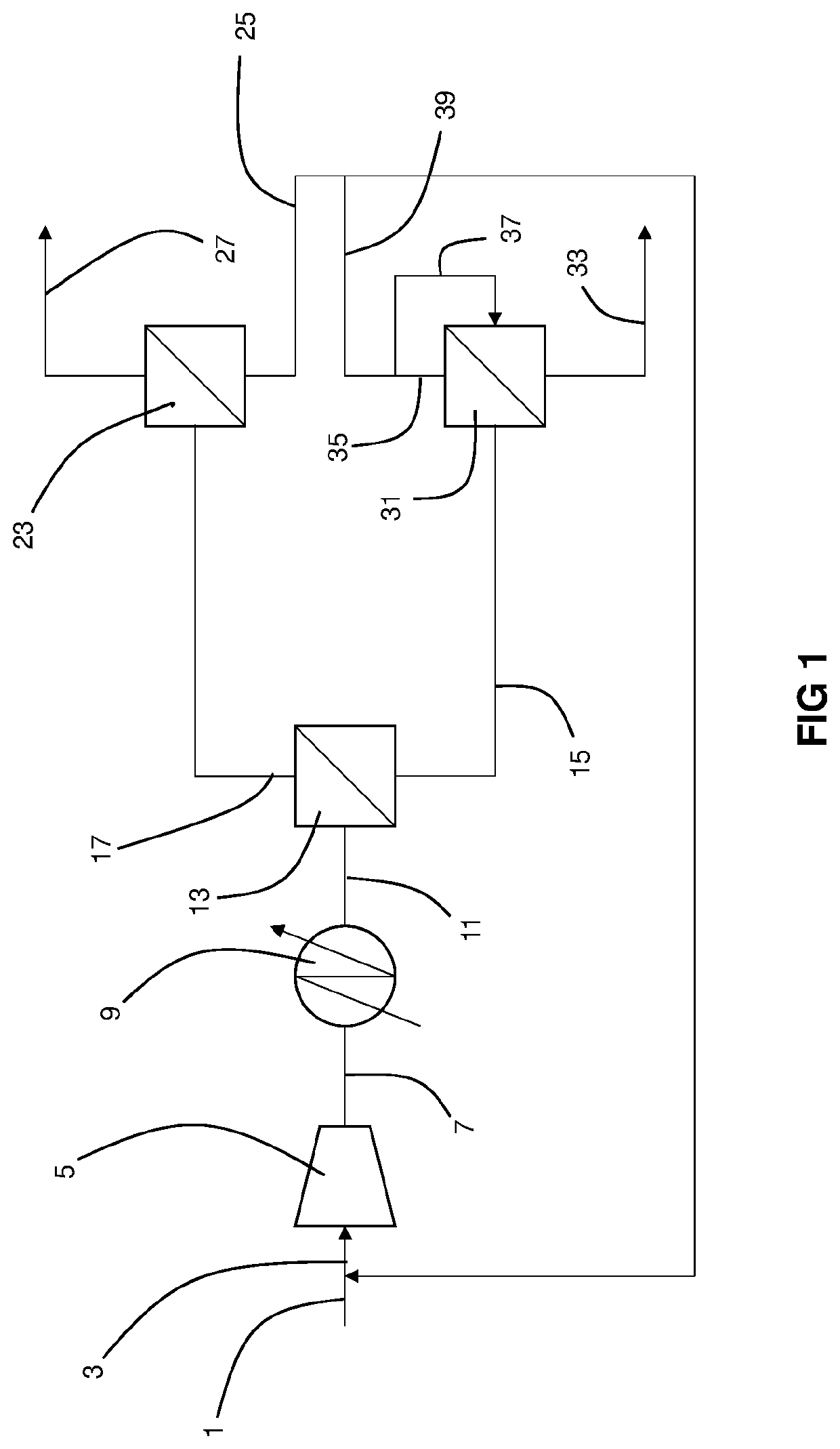
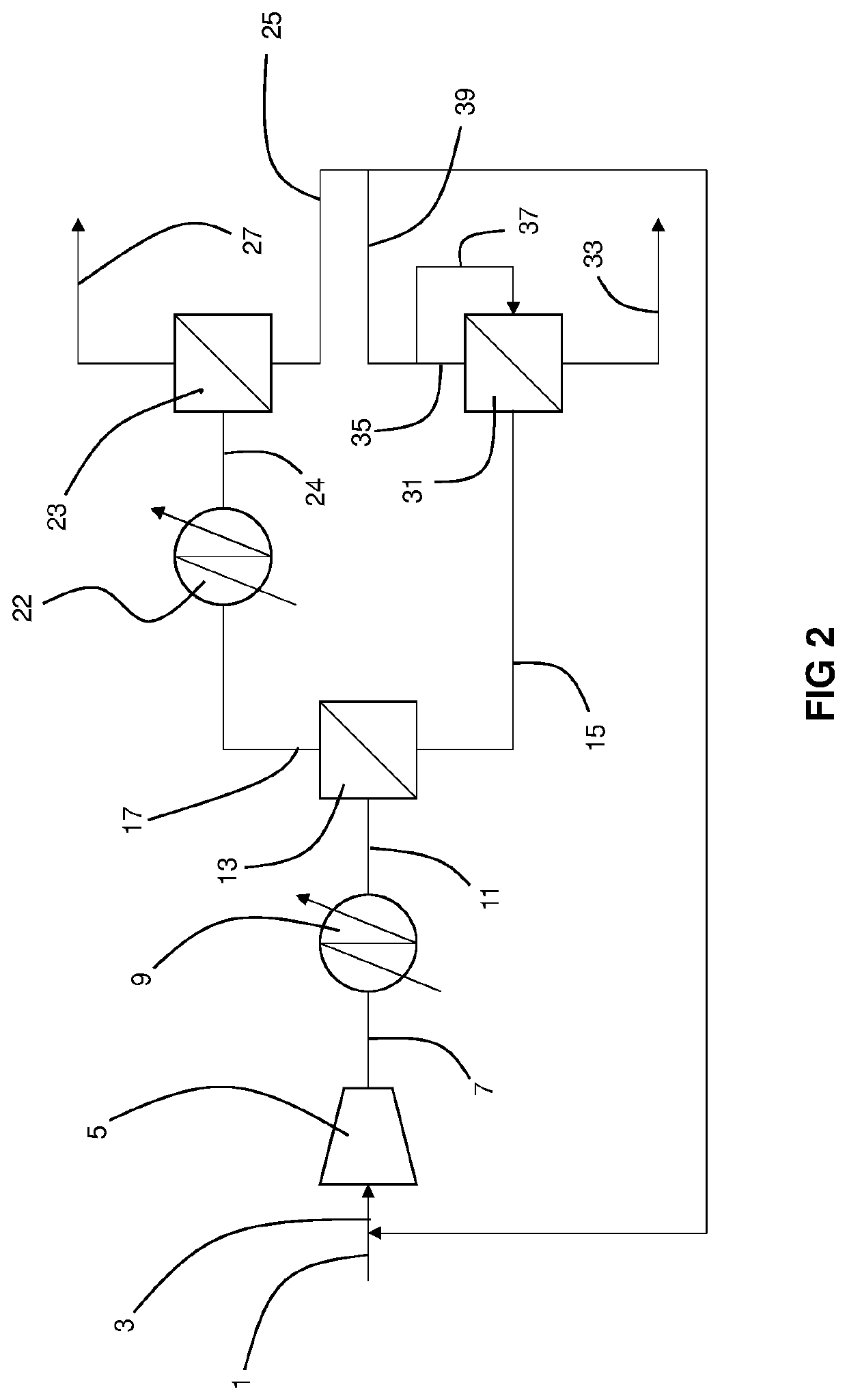
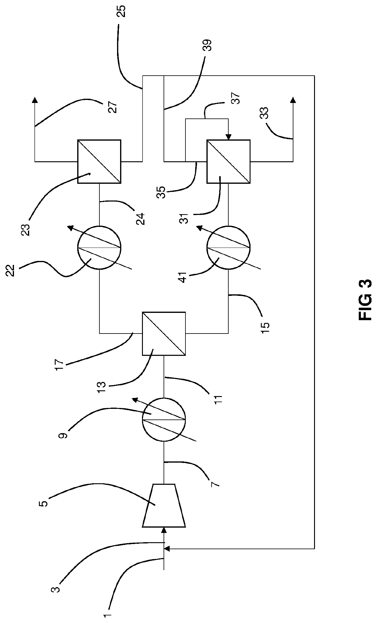
[0046]Separation of a gas mixture comprising first and second gases may be improved using three stages of gas separation membrane modules that includes the additional techniques of cooling the feed gas stream that is fed to the first stage and using a portion of the third stage retentate as a sweep gas on the third stage. Cooling the feed gas stream results in a lowered operating temperature of the polymeric membrane of the first stage. This lowered operating temperature increases the selectivity of the membrane for the second gas over the first gas. The loss of flux (productivity) of the second gas that would be expected from the point of view of the state of the art is more than compensated for by sweeping the third gas separation module with a portion of the retentate from that module. Surprisingly, the synergistic effect of these two techniques exceeds what might be expected by the skilled artisan from the combination of the effects of cooling alone and sweep alone.

[0047]The fir...


PUM

PropertyMeasurementUnit
vol %aaaaaaaaaa
vol %aaaaaaaaaa
temperatureaaaaaaaaaa

Abstract

Separation of a gas mixture comprising first and second gases may be improved using three stages of gas separation membrane modules that includes the additional techniques of cooling the feed gas stream that is fed to the feed stage and using a portion of the permeate stage retentate as a sweep gas on the permeate stage.

Description

CROSS-REFERENCE TO RELATED APPLICATIONS[0001]None.BACKGROUNDField of the Invention[0002]The present invention relates to a gas separation membrane-based system and method for purification of a gas mixture with improved membrane count / surface area.Related Art[0003]Gas separation membranes have long been used to separate a mixture of first and second gases into a product gas enriched in the first, valuable, gas and a vent gas enriched in the second, typically not as valuable, gas. In particular, the physical and chemical properties of the first and second gases and the material properties of the membrane (especially the separation layer of the membrane) are of primary importance in determining the fluxes of the first and second gases across the membrane.[0004]A particularly desirable separation is one in which the flux of one of the gases (such as the second gas) across the membrane is much higher than that of the other of the gases (such as the first gas). The membrane in this case i...

Claims


Application Information

Patent Timeline
Patent Type & Authority Applications(United States)
IPC IPC(8): B01D53/22B01D71/64
CPCB01D53/226B01D53/229B01D53/228B01D2325/20B01D2257/504B01D2256/245B01D2053/221B01D71/64F25D17/02B01D65/02C10L3/104B01D2321/18B01D53/225B01D2257/80B01D2257/708B01D2258/05Y02C20/40
Inventor MYRICK, GREGORY
Owner LAIR LIQUIDE SA POUR LETUDE & LEXPLOITATION DES PROCEDES GEORGES CLAUDE
Learn More