Electronegative gas electromigration membrane separation method

A gas separation and gas separation membrane technology, applied in separation methods, gas treatment, dispersed particle separation, etc., can solve the problem that the separation of electronegative gas and non-electronegative gas cannot be achieved, the absorption liquid needs subsequent treatment, and the increase of flue gas can be solved. humidity, etc.

Active Publication Date: 2018-11-16
WUHAN UNIV
View PDF10 Cites 0 Cited by
  • Summary
  • Abstract
  • Description
  • Claims
  • Application Information

AI Technical Summary

Problems solved by technology

The object of this method is SO 2 , NO and other small amounts of gas that can be absorbed by the absorption liquid, and migrate to the O on the surface of the absorption liquid 2 The electronegative gas that cannot be absorbed by the absorption liquid is precipitated from the absorption liquid again, and the separation of the electronegative gas and the non-electronegative gas cannot be realized; in order to realize SO 2 , NO rapid absorption, the absorption liquid is limited to KMnO 4 、H 2 o 2 etc. Specific can be compared with SO 2 , NO and other reagents that undergo rapid chemical reactions; this chemical reaction converts SO 2 , NO, etc. are fixed in the absorption liquid, and there is absorbed SO 2 , NO, etc. are difficult to comprehensively utilize, and the absorption liquid needs subsequent treatment; in addition, O 2 When the electronegative gas that cannot be absorbed by the absorption liquid is decomposed from the absorption liquid again, it will carry some water molecules and increase the humidity of the flue gas

Method used


Image

  • Electronegative gas electromigration membrane separation method

Examples


Embodiment Construction

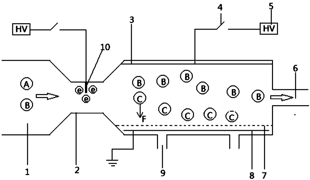
[0024] Below by embodiment, in conjunction with accompanying drawing, the technical scheme of the present invention is described further specifically, as figure 1 As shown, an electronegative gas electromigration membrane separation method includes the following steps, passing the electronegative and non-electronegative mixed gas to be separated into the gas separation device, and using the electron generator in the gas separation device to generate electrons , the electronegative gas in the mixed gas collides with electrons to generate stable negative ions or negative ion clusters, negative ions or negative ion clusters and uncharged non-electronegative gas enter the gas separation device together with the gas flow formed by the cathode and anode Electric field, a gas separation membrane is provided near the inner side of the anode in the electric field, and the negative ions or negative ion clusters penetrate through the gas separation membrane under the promotion of the elec...


PUM


Abstract

The invention provides an electronegative gas electromigration membrane separation method. To-be-separated electronegative and non-electronegative mixed gas is filled into a gas separation device; electrons are generated by utilizing an electron generator in the gas separation device; after electronegative gas in the mixed gas is collided with the electrons, stable negative ions or negative ion clusters are generated; the negative ions or the negative ion clusters enter an electric field consisting of a cathode and an anode in the gas separation device together with a gas flow; a gas separation membrane is arranged in the electric field closed to the inside of the anode; the negative ions or the negative ion clusters permeate and pass through the gas separation membrane under the pushing action of electric field force and a concentration difference between two sides of the gas separation membrane; and the gas passing through the gas separation membrane is further collected, so as to implement separation of the electronegative and non-electronegative mixed gas. By adopting the method provided by the invention, system resistance of membrane gas separation can be greatly reduced; themethod is particularly applicable to the separation of electronegative gas such as O2, H2S, SO2 and the like, and non-electronegative gas such as N2, H2 and the like; and low-energy-consumption high-efficiency separation of the gas can be implemented.

Description

technical field [0001] The invention belongs to the field of gas separation, in particular to an electronegative gas electromigration membrane separation method. Background technique [0002] Industrial gas is the basic raw material of modern industry. It is widely used in metallurgy, petroleum, chemical industry, medical treatment, environmental protection, machinery, military and other fields. It plays a strategic leading role in the development of the national economy and is known as the blood of industry. Gas separation is the main means of industrial gas preparation, and it has attracted more and more attention from all walks of life. [0003] Common gas separation methods include absorption, adsorption, and membrane separation. [0004] The absorption method is a method of gas separation based on the difference in the dissolution of each component in the mixed gas in a specific absorption liquid. According to whether the dissolved gas chemically reacts with the absorp...

Claims


Application Information

Patent Timeline
Patent Type & Authority Applications(China)
IPC IPC(8): B01D53/22B01D53/32
CPCB01D53/22B01D53/32B01D2257/104B01D2257/302B01D2257/304
Inventor 王祖武沈桂芬
Owner WUHAN UNIV
Why Eureka
Try Eureka