Dust hood device for a power tool and the use thereof, and method for dust collection

Pending Publication Date: 2022-07-14
HILTI AG
0 Cites 0 Cited by

AI-Extracted Technical Summary

Problems solved by technology

Most of the conventional dust hoods which are known from the prior art are produced from plastic and cannot be adapted to different ambient conditions or working and/or operating parameters of the power tool, which is a disadvantage.
The disadvantage with these conventional dust hoods is that the extraction behavior thereof cannot be adapted to possibly changing ambient conditions or to working and/or operating parameters of the power tool.
In this context, power tools with disk-shaped work-performing means in which the work-performing means rotates in the sam...

Benefits of technology

[0046]For the purposes of the invention, it is preferred that, for mounting on the blade guard of the power tool, the two halves of the dust hood device are separated from one another and pushed apart by screwing on the fastening means. The pushing apart of the two halves is made easier by a linear guide. The guide can be formed, for example, by a dome on one half of the dust hood device and a corresponding hole in the other half of the dust hood device, which can interact with one another. In this case, a maximum spacing of the two halves can be set or limited by the use of at least one retaining washer. For the purposes of the invention, it is particularly preferred that two retaining washers are used, which are arranged on a common shaft. The shaft with the retaining washers advantageously prevents the two halves of the dust hood device from being completely separated from one another. In other words, the shaft with the retaining washers represents a safeguard against the loss of the two halves of the dust hood device with respect to one another. For the purposes of the invention, it is preferred that the halves of the dust hood device can be pushed onto the dust hood of a power tool after having been pushed apart. The two halves of the extraction device can then be connected to one another again. Another advantage of the invention consists in that positive engagement with a mating contour is formed by the connection of the two halves of the extraction device, by means of which positive engagement fastening of the extraction device on the blade guard of a power tool can be made significantly easier. This positive engagement can preferably be formed when the fastening means is tightened, with the result that the dust hood device is connected firmly to the blade guard or the work-performing means dust hood of the power tool.
[0047]Wheels can furthermore be provided on the shaft, which forms the safeguard against loss together with the retaining washers, to enable the device to be moved over the substrate more easily. The wheels advantageously enable the user to make the power tool roll over the substrate with surprisingly little expenditure of force during operation. It is thereby possible, in particular, to avoid the dragging over the substrate which is common with conventional power tools. Moreover, the wheels can be used as a pivot point to enable simple and defined penetration into ...

Abstract

A dust hood device for a power tool and to the use thereof and to a method for dust collection. The dust hood device includes, on the lower side thereof, various openings, through which a mixture of air and dust formed during work with the power tool can be extracted. Also disclosed is the use of a dust hood, in particular at various working depths of the power tool, and to a method for dust collection, wherein opening and closing of the openings of the dust hood device can be controlled in accordance with the working depth of the power tool.

Application Domain

Technology Topic

Image

  • Dust hood device for a power tool and the use thereof, and method for dust collection
  • Dust hood device for a power tool and the use thereof, and method for dust collection
  • Dust hood device for a power tool and the use thereof, and method for dust collection

Examples

  • Experimental program(1)

Example

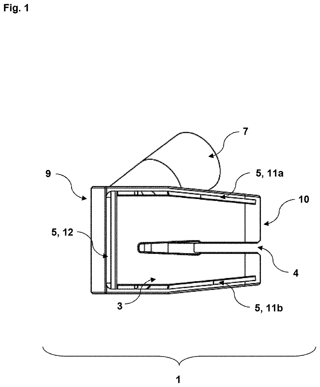
[0062]FIG. 1 shows a lower side (3) of a preferred embodiment of the dust hood device (1). The power tool (2) on which the dust hood (1) can be secured is not illustrated in the figures. The dust hood device (1) has various openings (4, 5, 11a, 11b, 12) on the lower side (3) thereof. A first opening (4) is formed, for example, by a main channel, which serves at least in part as an insertion slot for the work-performing means (18) of the power tool (2). This insertion slot (4) is preferably open both in the full cutting mode and in the cutting-in mode of the power tool (2). On its lower side (3), the dust hood device (1) furthermore comprises a second opening (5), which can be formed by side channels (11a, 11b) and a front slotted opening (12). The slotted opening (5) preferably extends substantially parallel to a front edge of the dust hood device (1). For the purposes of the invention, it is preferred that the slotted opening (12) is present in a front region of the dust hood device (1), wherein the dust hood device (1) is delimited in the front region (9) by a rounded outer wall (13) or front side. The rear side (10) of the dust hood device (1) can preferably be level or flat. The side channels (11a, 11b) are arranged substantially perpendicular to the front slotted opening (12), but this is separate from the front slotted opening (12) in the interior of the dust hood (1). In particular, the front slotted opening (12) feeds a first air channel (14), while the side channels (11a, 11b) and the main channel (4) feed a second air channel (15) of the dust hood device (1). In an upper region of the dust hood (1), the air channels (14, 15) {see,e.g., FIG. 3) open into an extraction nozzle (7), which can be connected to a vacuum cleaning device. Via the extraction nozzle (7), the dust hood device (1) can advantageously be subjected to a vacuum, using the vacuum cleaning device, wherein the vacuum is distributed particularly uniformly in the interior (6) of the dust hood (1) by virtue of the arrangement of the guide element (8). It is thereby advantageously possible to provide uniform pressure conditions and intake forces in the air channels (14, 15) and in the openings (4, 5, 11, 12) which are assigned to the air channels (14, 15).
[0063]FIG. 2 shows a side view of a preferred embodiment of the dust hood device (1). In particular, FIG. 2 shows a dust hood (1) which has an extraction nozzle (7) on a side facing the observer, while, on a side facing away from the observer, the dust hood (1) has a preferably lever-type fastening means (19), by means of which the dust hood device (1) can be secured on a power tool (2). Through the opening in the upper region of the fastening means (19) it is possible, for example, to pass a screw as a connecting means, by means of which the dust hood (1) can be secured on another dust hood of the power tool (2) or on a blade guard of the work-performing means (18) of the power tool (2).
[0064]In the exemplary embodiment of the invention which is illustrated in FIG. 2, the dust hood (1) is bounded toward the outside by a casing (20), wherein the casing (20) can be formed by two mutually corresponding halves, for example. Owing to the provision of the extraction nozzle (7), the two halves of the casing (20) of the dust hood (1) are preferably not formed symmetrically with one another. For the purposes of the invention, it is preferred, in particular, that the first opening (4) (see, e.g., FIG. 1) of the dust hood device (1) is not arranged centrally on the lower side (3) thereof but that the half of the casing (20) of the dust hood (1) which comprises the extraction nozzle (7) is of somewhat wider design than the half of the casing (20) of the dust hood device (1) which comprises the fastening means (19). In particular, the casing (20) of the dust hood device (1) surrounds an interior space (6) which, for the purposes of the invention, is preferably also referred to as the «interior» of the dust hood device (1).
[0065]Illustrated on the left-hand side of FIG. 2 is the front region (9) of the dust hood (1), which is delimited, in particular, by a front outer wall (13) or front wall of the dust hood device (1). In particular, FIG. 2 shows the rounded design of the front region (9) of the dust hood device (1). The rear side (10) of the dust hood device (1) is illustrated on the right-hand side of FIG. 2, wherein the rear side (10) of the dust hood (1) is preferably of flat design.
[0066]FIG. 3 shows a sectional view of a preferred embodiment of the proposed dust hood device (1). In particular, FIG. 3 shows the guide element (8) or the position thereof in the interior (6) of the exemplary embodiment of the proposed dust hood device (1) which is illustrated in FIG. 3. Starting from the lower side (3) of the dust hood device (1), the guide element (8) extends in the direction of the extraction nozzle (7) and separates a first air channel (14) from a second air channel (15). The first air channel (14) is preferably arranged in the front region (9) of the dust hood (1). The second air channel (15) preferably comprises an extraction region (16) and a collecting region (17). The extraction region (16) preferably forms the upper region of the second air channel (15), which merges into the extraction nozzle (7). The collecting region (17) of the second air channel (15) preferably extends substantially parallel to the lower side (3) of the dust hood device (1) and, in particular, above the side channels (11a, 11b) and above the main channel (4), in which the work-performing means (18) of the power tool (2) may be situated, at least in part. The first air channel (14) preferably extends between the guide element (8) and the front wall (13) of the dust hood device (1). The lower outlet of the first air channel (14) preferably forms a section of the second opening (5) of the proposed dust hood (1), in particular the front slotted opening (12)(see. E.g., FIG. 1).
[0067]The front slotted opening (12) can have a width of 5 to 10 mm, for example, wherein a width of 7.5 mm has proven particularly advantageous for the extraction behavior of the dust hood (1). The side channels (11a, 11b) preferably have a width of 1 to 5 mm, wherein, in particular, a width of 3 mm allows effective dust collection here. The central tool opening channel (4) can preferably have a width of 2 to 10 mm, wherein a width of 6 mm is particularly preferred. It has been found that a particularly good dust collection and extraction behavior of the dust hood device (1) is achieved with a combination of the width of the slotted opening (12) of 7.5 mm, of the side channels (11a, 11b) of 3 mm and of the first opening (4) of 6 mm.
[0068]FIG. 3 furthermore shows the device (19), preferably of lever-type design, for securing the dust hood device (1) on the power tool (2), and the rear side (10) of the dust hood (1).
[0069]FIG. 4 shows an oblique view of a preferred embodiment of the proposed dust hood device (1). In addition to the objects already shown in the previous figures, FIG. 4 shows, in particular, a possible preferred structuring or configuration of the lower side (3) of the dust hood device (1). The side channels (11a, 11b) are arranged at the sides of the lower side (3), illustrated in FIG. 4, of the dust hood (1). Arranged in a front region (9) of the dust hood device (1) there is preferably a slotted opening (12), which, together with the side channels (11a, 11b), forms the second opening (5) for the purposes of the invention, wherein this second opening (5) can be closed in the full cutting mode of the power tool (2), for example. Beginning in the transitional region between the side channels (11a, 11b) and the front slotted opening (12) there is the guide element (8), which extends into the interior (6) of the dust hood device (1) and there separates the two air channels (14, 15) from one another.
[0070]In the rear region (10) of the dust hood device (1), the first opening (4) first of all has substantially parallel lateral edges. In this region of the first opening (4), the work-per-forming means (18) of the power tool (2) can rotate when the proposed dust hood device (1) is present in a manner connected to a power tool (2). This region of the first opening (4) is preferably referred to as the rear section or as the work-performing means region of the first opening (4). Subsequently—in the direction of the front region (9) of the dust hood device (1)—the first opening (4) widens. This region of the first opening (4) is preferably referred to as the extraction region or front region of the first opening (4) of the proposed dust hood (1). The rear region of the first opening (4) is preferably designed to at least partially accommodate the work-performing means (18) of the power tool (2), while the front region of the first opening (4) is used for dust collection, namely preferably both in the cutting-in mode and in the full cutting mode. The dust-air mixture sucked in through the first opening (4) is conveyed in the direction of the extraction nozzle (7) through the second air channel (15) together with the dust-air mixture sucked in through the side channels (11a, 11b), while the dust-air mixture which is sucked in through the front slotted opening (12) is conveyed in the direction of the extraction nozzle (7) through the first air channel (14) in the front region (9) of the dust hood device (1).
[0071]FIG. 5 shows a view of a preferred embodiment of the proposed dust hood device (1) in conjunction with a work-performing means (18) of a power tool (2). In particular, FIG. 5 shows a possible orientation of the work-performing means (18) and the dust hood (1) relative to one another. For example, the work-performing means (18), illustrated in figure 5, of the power tool (2) rotates within the rear region of the first opening (4) of the dust hood device (1), while the front region of the first opening (4) remains substantially free in order to be able to collect dust. Furthermore, FIG. 5 shows the second opening (5) and a possible arrangement of this second opening (5) on the lower side (3) of the illustrated dust hood (1). The dust hood device (1) can be secured by a fastening means (19) on the power tool (2) or on a further dust hood of the power tool (2) or on a blade guard for the work-performing means (18) of the power tool (2). According to a particularly preferred embodiment of the invention, the work-performing means (18) illustrated in FIG. 5 can be a saw blade, which can be secured on a saw as a power tool (2).
[0072]FIG. 6 shows various views of a preferred embodiment of the proposed dust hood device (1) with a conical extraction nozzle (7). Moreover, FIG. 6 illustrates the fastening means (21), which connects the two halves of the dust hood device (1) to one another. The fastening means (21) can preferably be designed as a screw and can comprise a star knob. FIG. 6 furthermore illustrates the wheels (24) of the dust hood device (1). These can be arranged on a shaft (22), on which the retaining washers (23), which form the safeguard against loss of the dust hood device (1) together with the shaft (22), can be arranged.
[0073]FIG. 7 shows a plan view of a preferred embodiment of the proposed dust hood device (1). The extraction nozzle (7), the wheels (24) as well as the shaft (22) with the retaining washers (23) and the fastening means (21) having a star knob are clearly visible in FIG. 7.
[0074]FIG. 8 shows various views of a preferred embodiment of the proposed dust hood device (1) with an extraction nozzle (7) configured in an alternative way.
[0075]FIG. 9 shows a view of a preferred embodiment of the proposed dust hood device (1) in conjunction with a work-performing means (18) of a power tool (2). It furthermore illustrates the shaft (22) with the retaining washers (23), the wheels (24), which can preferably be on the same shaft (22) as the retaining washers (23), and the screw (21) with the star knob.
LIST OF REFERENCE SIGNS
[0076]1 Dust hood device or dust hood
[0077]2 Power tool
[0078]3 Lower side of the dust hood
[0079]4 First opening
[0080]5 Second opening
[0081]6 Interior space of the dust hood
[0082]7 Extraction nozzle
[0083]8 Guide element
[0084]9 Front region of the dust hood
[0085]10 Rear region of the dust hood
[0086]11a, b Side channels
[0087]12 Front slotted opening
[0088]13 Front outer wall of the dust hood, front side
[0089]14 First air channel
[0090]15 Second air channel
[0091]16 Upper extraction channel
[0092]17 Collecting region
[0093]18 Work-performing means of the power tool
[0094]19 Fastening means
[0095]20 Casing of the dust hood
[0096]21 Screw with star knob
[0097]22 Shaft
[0098]23 Retaining washers
[0099]24 Wheels

PUM

PropertyMeasurementUnit
Time1.0s
tensileMPa
Particle sizePa
strength10

Description & Claims & Application Information

We can also present the details of the Description, Claims and Application information to help users get a comprehensive understanding of the technical details of the patent, such as background art, summary of invention, brief description of drawings, description of embodiments, and other original content. On the other hand, users can also determine the specific scope of protection of the technology through the list of claims; as well as understand the changes in the life cycle of the technology with the presentation of the patent timeline. Login to view more.

Similar technology patents

Scouring pad

Owner:3M INNOVATIVE PROPERTIES CO

Data receiving device

ActiveUS7277501B2Reduce timeEasily makeFrequency/rate-modulated pulse demodulationAmplitude-modulated carrier systemsFrequency bandQuadrature signal
Owner:PANASONIC CORP

Classification and recommendation of technical efficacy words

  • Easily make
  • Easily move

Data-handling, business systems and games

InactiveUS20060030402A1Competitiveness be decreaseEasily makeVideo gamesCommerceMonetary AmountBank account
Owner:CHANDRAKUMAR APPUTHURAI +1

Collapsible metal air battery

InactiveUS20070154766A1Easily makeEffectively dischargeFuel and primary cellsDeferred-action cellsMagnesiumEngineering
Owner:BAIK DONG SOO +1

Canine Vest

InactiveUS20120024239A1Quickly and easily placeEasily moveSafety beltsAnimal housingEngineering
Owner:FORBES WILLIAM CHARLES
Why Eureka
Try Eureka