Circuit device and filter circuit
- Summary
- Abstract
- Description
- Claims
- Application Information
AI Technical Summary
Benefits of technology
Problems solved by technology
Method used
Image

Examples
embodiment 1
Preferred Embodiment 1
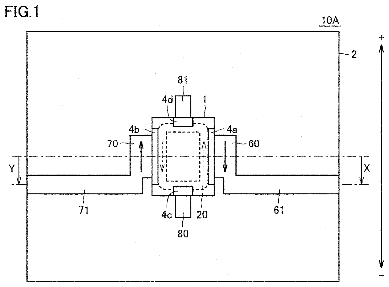
[0024]First, a circuit device 10A according to Preferred Embodiment 1 of the present invention will be described with reference to the drawings. FIG. 1 is a plan view of the circuit device 10A according to Preferred Embodiment 1. A coil component 1 is mounted on a surface of a substrate 2 of the circuit device 10A. Land electrodes 60, 70, 80, and 81 on which the coil component 1 is surface-mounted are provided on the surface of the substrate 2. The land electrode 60 is connected to an electrode 4a that is an output terminal to output a current from the coil component 1, and the land electrode 70 is connected to an electrode 4b that is an input terminal to input the current to the coil component 1. The direction of the current flowing through the coil component 1 may be changed such that the current is inputted through the electrode 4a as the input terminal and is outputted through the electrode 4b as the output terminal.
[0025]The land electrode 80 is connected ...
embodiment 2
Preferred Embodiment 2
[0065]In the circuit device 10A according to Preferred Embodiment 1, the wiring lines 61 and 71 are formed in advance at positions shifted by the shifting value X (first distance) relative to the land electrodes 60 and 70. A circuit device according to Preferred Embodiment 2 of the present invention has a configuration in which a connecting position of a wiring line to a land electrode may be changed at the time of mounting the component. FIGS. 7A and 7B are plan views of the circuit device according to Preferred Embodiment 2. In the circuit device in FIGS. 7A and 7B, the same or corresponding components as those of the circuit device 10A in FIG. 1 are denoted by the same reference signs, and detailed description thereof will not be repeated. Dashed-and-dotted lines in FIGS. 7A and 7B represent the center of the side surface of the coil component 1 and the wiring lines, and a lower side in the drawing is defined as the minus (negative) direction and an upper si...
embodiment 3
Preferred Embodiment 3
[0078]In Preferred Embodiment 2, described is the configuration in which, at the time of mounting the component, the connection element 90 can electrically connect the connection portion 62a and the end portion 63a or the connection portion 62b and the end portion 63b, and the connection element 91 can electrically connect the connection portion 72a and the end portion 73a or the connection portion 72b and the end portion 73b. In Preferred Embodiment 3 of the present invention, a configuration of a circuit device in which whether or not to include the coil component 1 can be determined at the time of mounting the component will be described.
[0079]FIGS. 9A and 9B are plan views of the circuit device according to Preferred Embodiment 3. FIG. 9A is a plan view of a circuit device 18A on which the coil component 1 is mounted, and FIG. 9B is a plan view of a circuit device 18B on which the coil component 1 is not mounted. In the circuit device 18A and the circuit de...
PUM
 Abstract
Description
Claims
Application Information
 - R&D Engineer
- R&D Manager
- IP Professional
- Industry Leading Data Capabilities
- Powerful AI technology
- Patent DNA Extraction
Browse by: Latest US Patents, China's latest patents, Technical Efficacy Thesaurus, Application Domain, Technology Topic.
© 2024 PatSnap. All rights reserved.Legal|Privacy policy|Modern Slavery Act Transparency Statement|Sitemap