
Camera module and camera device comprising same

Pending Publication Date: 2022-07-28
LG INNOTEK CO LTD
View PDF0 Cites 0 Cited by
  • Summary
  • Abstract
  • Description
  • Claims
  • Application Information

AI Technical Summary

Benefits of technology

The present invention solves problems in the design and evaluation of camera modules by separating the first barrel assembly and first mover, improving design easiness and reducing manufacturing costs. Additionally, the invention uses an inductive change to improve position detection accuracy and a resonator to provide excellent linearity and hysteresis even when the lens movement distance is increased. Furthermore, the invention addresses the issue of friction torque generation during zooming, providing a solution for this problem.

Problems solved by technology

In addition, recent camera modules employ Image Stabilization (IS) technology to correct or prevent image shake due to camera movement caused by unstable fixing devices or user movement.
However, the Hall sensor as described above has linearity when the lens movement distance is small, but has a problem in that the linearity decreases as the lens movement distance increases.
In addition, the Hall sensor is greatly affected by a surrounding environment, and in particular, has a problem of poor reliability due to heat generated when the camera module is driven.

Method used


Image

  • Camera module and camera device comprising same
  • Camera module and camera device comprising same
  • Camera module and camera device comprising same

Examples


embodiment

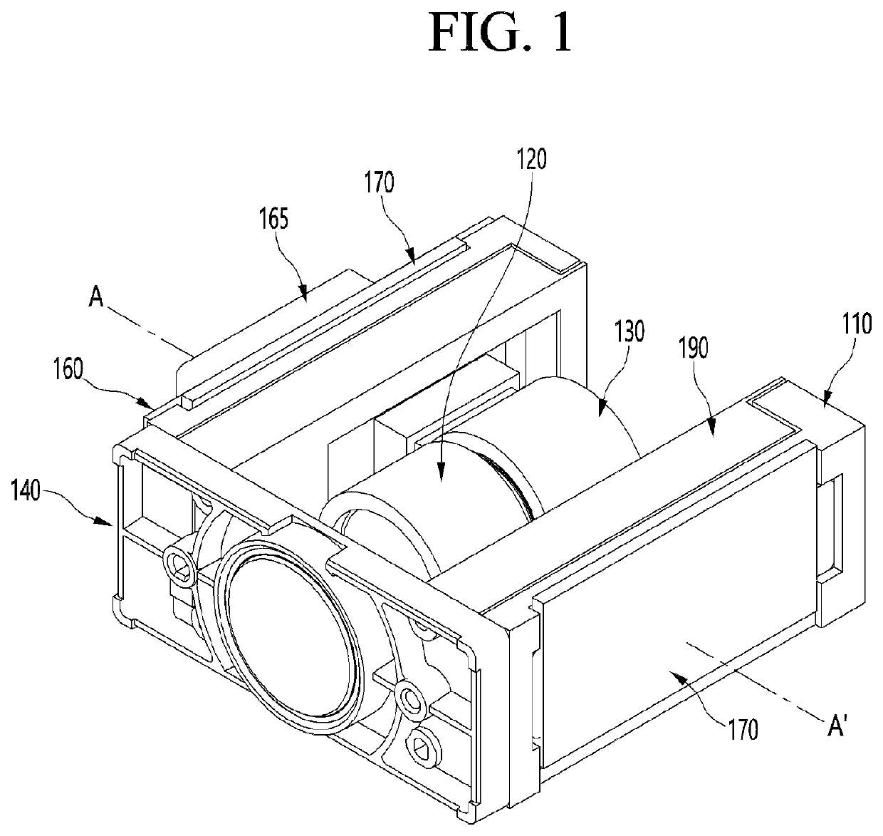
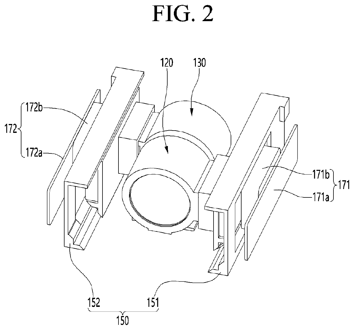
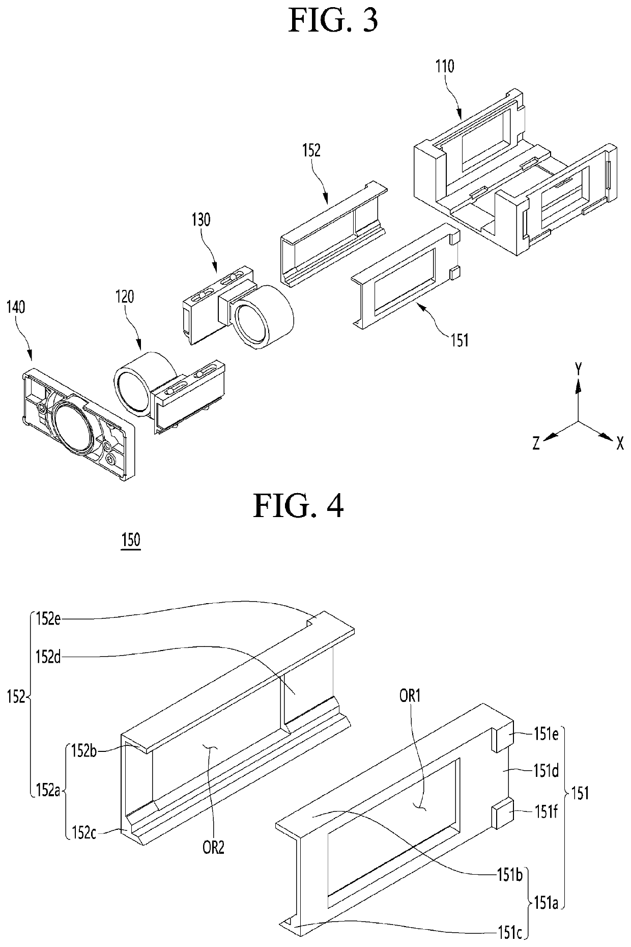
[0119]FIG. 1 is a perspective view of a camera module according to an embodiment, FIG. 2 is a perspective view in which some components are omitted from the camera module according to the embodiment shown in FIG. 1, and FIG. 3 is an exploded perspective view in which some components are omitted from the camera module according to the embodiment shown in FIG. 1.

[0120]Referring to FIG. 1, a camera module 100 according to an embodiment may include a base 110, a substrate 160 disposed on an outer side of the base 110, a driver IC 165 disposed on one surface of the substrate 160, a first lens assembly 120, a second lens assembly 130, a third lens assembly 140, a driving portion 170, and a guide cover 190.

[0121]FIG. 2 is a perspective view in which the base 110, the substrate 160, the guide cover 190, and the driver IC 165 are omitted in FIG. 1, and referring to FIG. 2, the camera module according to the embodiment may include a guide portion 150 including a first guide portion 151 and a ...


PUM


Abstract

A camera module according to an embodiment includes base; a guide portion disposed on an inner side of the base; a lens assembly moving along the guide portion; and a substrate disposed on an outer side of the base, wherein the lens assembly includes a conductor disposed under a lower surface thereof, and wherein the substrate includes a resonance coil disposed in a region facing the lower surface of the lens assembly and overlapping at least a part of the conductor in a direction perpendicular to an optical axis direction in response to movement of the lens assembly.

Description

TECHNICAL FIELD[0001]An embodiment relates to a camera module and a camera device comprising the same.BACKGROUND ART[0002]The camera module captures a subject and stores it as an image or video, and is installed in mobile terminals such as cell phones, laptops, drones, and vehicles.[0003]On the other hand, portable devices such as smartphones, tablet PCs, and laptops have built-in micro camera modules, and such a camera module may perform an autofocus (AF) function that automatically adjusts a distance between an image sensor and a lens to align the focal lengths of the lenses.[0004]In addition, recent camera modules may perform a zooming function of zooming up or zooming out by increasing or decreasing a magnification of a distant subject through a zoom lens.[0005]In addition, recent camera modules employ Image Stabilization (IS) technology to correct or prevent image shake due to camera movement caused by unstable fixing devices or user movement.[0006]The image stabilization (IS) ...

Claims


Application Information

Patent Timeline
IPC IPC(8): H04N5/225G03B13/36
CPCH04N5/2253G03B13/36H04N5/2254G03B5/00G02B7/09G02B27/646G03B30/00G03B2205/0069G03B3/10H04N23/57H04N23/55H04N23/54
Inventor JANG, YOUNG BAEJANG, DAE SIKKIM, CHULROH, HYUN GYU
Owner LG INNOTEK CO LTD
Learn More