
Thin-blade chisel system

Pending Publication Date: 2022-08-04
MEDMETALEX CO LTD
View PDF0 Cites 0 Cited by
  • Summary
  • Abstract
  • Description
  • Claims
  • Application Information

AI Technical Summary

Benefits of technology

The invention allows for a force to be applied to the blade tip in a way that separates the implant from the bone safely and efficiently. This increases the likelihood of success in revision surgeries and avoids damage to the bone.

Problems solved by technology

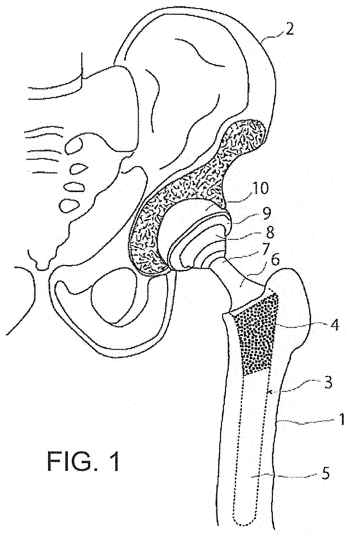
The revision surgery may become necessary, owing to the loosening of the implant after the surgery, infection of the operated part, or a disease of another part of the patient.
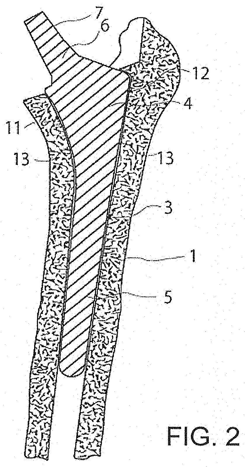
Since the implant is firmly combined with the bone, it is not easy to separate the outer surface of the implant and the inner surface of the bone from each other.
Accordingly, an existing thin-blade chisel often fails to separate the outer surface of the implant and the inner surface of the bone from each other efficiently, quickly, and safely, owing to discordance in shape from the gap, or a damage in the bone resultant from the use of the chisel while neglecting the discordance.
In many such cases, additional trouble and time are required, for the restoration of the damaged bone.
However, when the hammering timing is wrong, the bone or the thin-blade chisel itself may be broken, and therefore efficiently and safely cutting the bone-conglutinated part 13 apart is an extremely difficult job that requires high expertise.

Method used


Image

  • Thin-blade chisel system
  • Thin-blade chisel system
  • Thin-blade chisel system

Examples


Embodiment Construction

[0046]Hereafter, embodiments of the present invention will be described in detail, with reference to the drawings. It should be noted that the following embodiments are essentially preferable examples, and not intended to limit the object to which the present invention is applied, or the scope of its use.

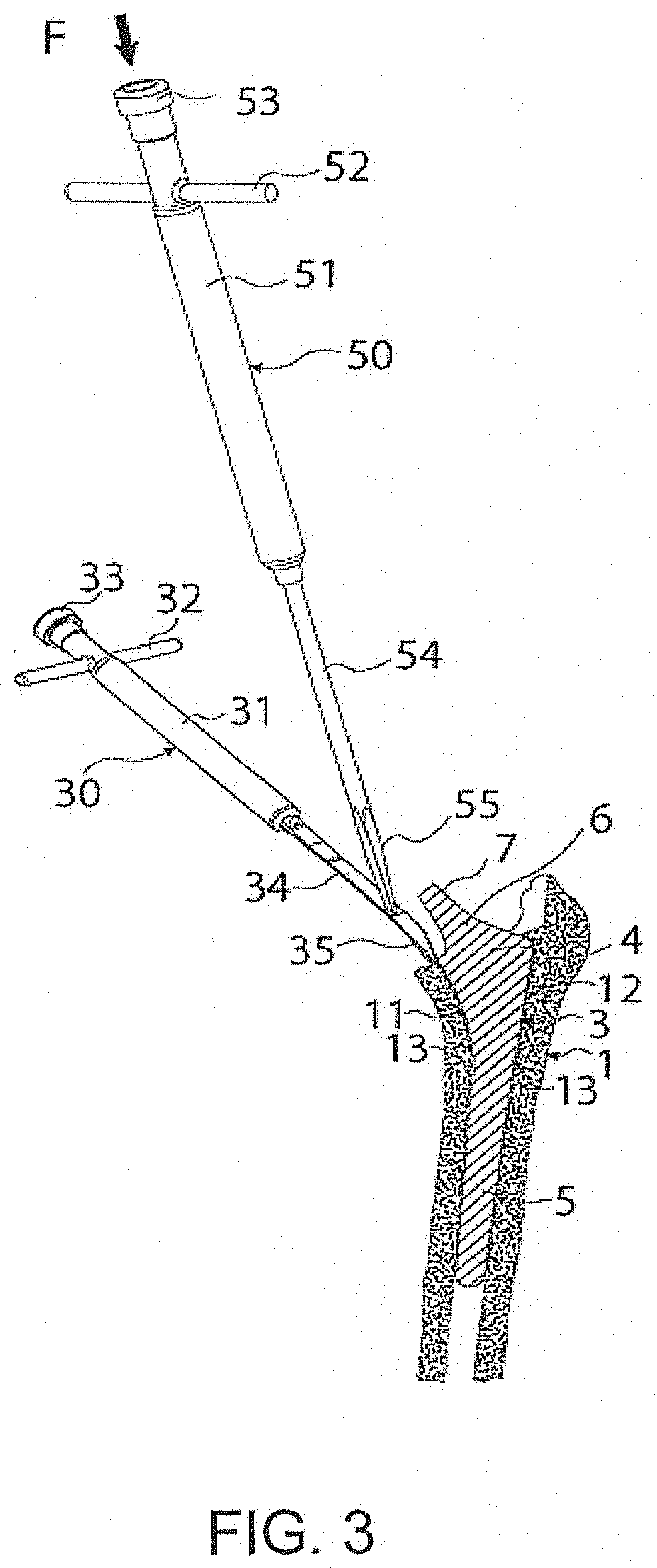
[0047]FIG. 3 to FIG. 8 illustrate a thin-blade chisel system according to a first embodiment, and a thin-blade chisel, a hammering direction changing tool, and so forth employed in the first embodiment.

[0048]The thin-blade chisel 30 in the thin-blade chisel system includes a hammering portion 33, a handle 32, a holding shaft portion 31, a shaft plate 34, and a blade tip 35. The blade tip 35 is curved so as to tilt forward. This curve is formed in accordance with the curve of the proximal inner portion 11, and various patterns are prepared for different shapes of the implant. For the proximal outer portion 12, a straight blade is employed, instead of the one tilted forward as shown i...


PUM


Abstract

A thin-blade chisel system, for separating an outer surface of an orthopedic implant and an inner surface of a bone from each other, includes a thin-blade chisel having a blade tip at a distal end portion in a longitudinal direction, and a hammering direction changing tool engaged with the thin-blade chisel to apply a force in an advancing direction of the blade tip. The thin-blade chisel includes a hammering blow-receiving part, preferably a through hole penetrating in a thickness direction, at a predetermined position on a proximal side closer to the surgeon. The hammering direction changing tool includes a hammering portion to be hammered, located at a proximal end portion, and a recess formed at a distal end portion, to be engaged with an inner circumferential surface of the through hole.

Description

FIELD OF THE INVENTION[0001]The present invention relates to a thin-blade chisel system for separating an outer surface of an orthopedic implant planted inside a bone, and the inner surface of the bone, from each other. The present invention also relates to the thin-blade chisel and a hammering direction changing tool employed in the system.BACKGROUND OF THE INVENTION[0002]Various types of artificial joints for curing a disease of a joint, such as a hip joint or a knee joint, and also artificial bones for curing bones other than the joint, have been developed, and are employed for actual clinical treatment. For example, an orthopedic implant, called a fully artificial hip joint, is employed for treatment of a disease of coxarthrosis, and in this case a hip joint stem (orthopedic implant) to be planted in a femur medullary cavity in place of the excised femur is employed, and a semispherical shell (orthopedic implant) is fixed to an acetabular roof, reamed in a dome shape, on the sid...

Claims


Application Information

Patent Timeline
IPC IPC(8): A61B17/16A61F2/46
CPCA61B17/1604A61F2/4607A61B17/1668A61B17/1666A61F2/4609A61F2/32A61F2/34A61F2002/4619A61F2002/4681A61F2/46A61B17/16A61F2/28
Inventor AMINO, HIROKAZU
Owner MEDMETALEX CO LTD
Learn More