

A light emitting device
a technology of light beams and light beams, which is applied in the direction of semiconductor devices, lighting and heating devices, instruments, etc., can solve the problems of not being able to project a well-defined image, all of the known concepts for remote adjustment of light beams are either expensive or require a lot of effort to construct and maintain over a considerable lifetim
- Summary
- Abstract
- Description
- Claims
- Application Information
AI Technical Summary
Benefits of technology
Problems solved by technology
Method used
Image

Examples
first embodiment
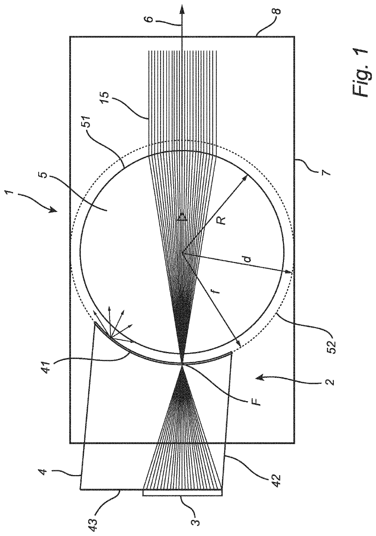
[0066]FIG. 1 shows a cross-sectional side view of a light emitting device 1 according to the invention.
[0067]Generally, and irrespective of the embodiment, the light emitting device 1 is of the type adapted for projecting a light beam 15 onto a target surface. The light emitting device 1 comprises at least one light engine 2. The light engine 2 comprises one or more light sources 3, at least one light mixing chamber 4 and an optical component 5. The optical component 5 has a spherical shape.
[0068]Generally, and irrespective of the embodiment, when seen along the optical axis 6 of the light emitting device 1, the at least one light mixing chamber 4 is arranged between the at least one light source 3 and the spherical optical component 5.
[0069]The light emitting device may furthermore comprise a housing 7 with a front window 8. The housing 7 may be a black absorbing housing or tube. The front window 8 is transparent and may for example be made of clear polycarbonate or textured PMMA, ...
second embodiment
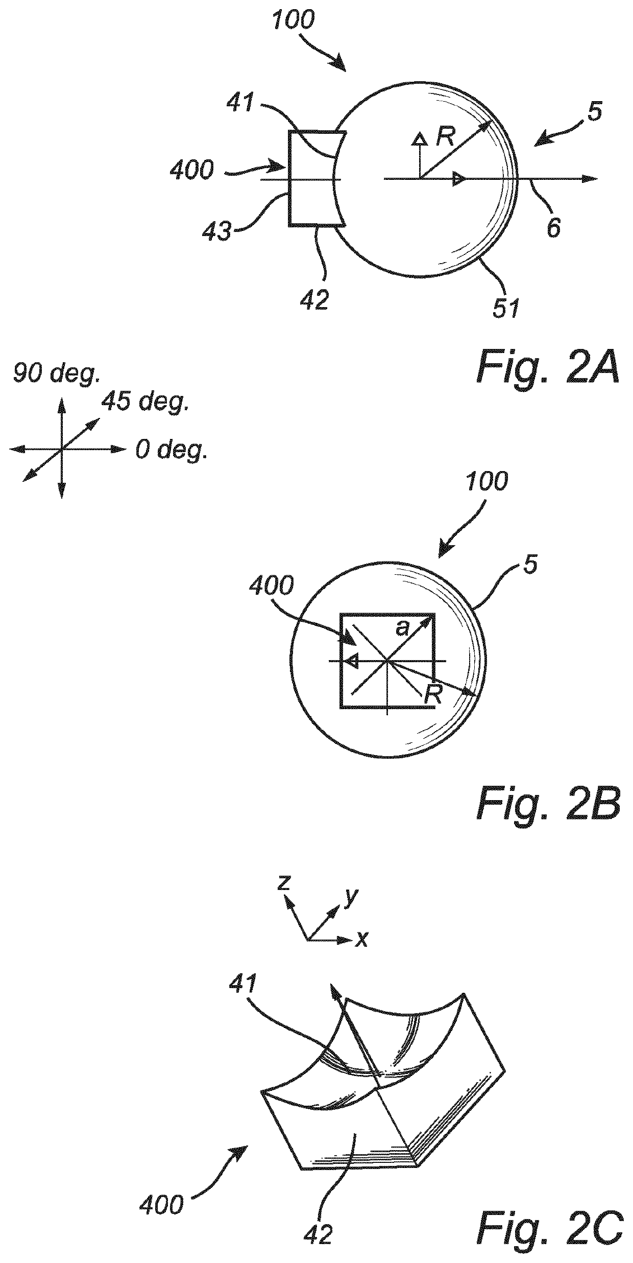
[0079]FIG. 2A shows cross-sectional side view of a light emitting device 100 according to the invention. FIG. 2B shows a bottom view of the light emitting device 100 according to FIG. 2A, and FIG. 2C shows a perspective view of a light mixing chamber of the light emitting device 100 according to FIG. 2A. The light emitting device 100 differs from that of FIG. 1 described above in that the light mixing chamber 400 of the light emitting device 100 is provided with a square cross-sectional shape.
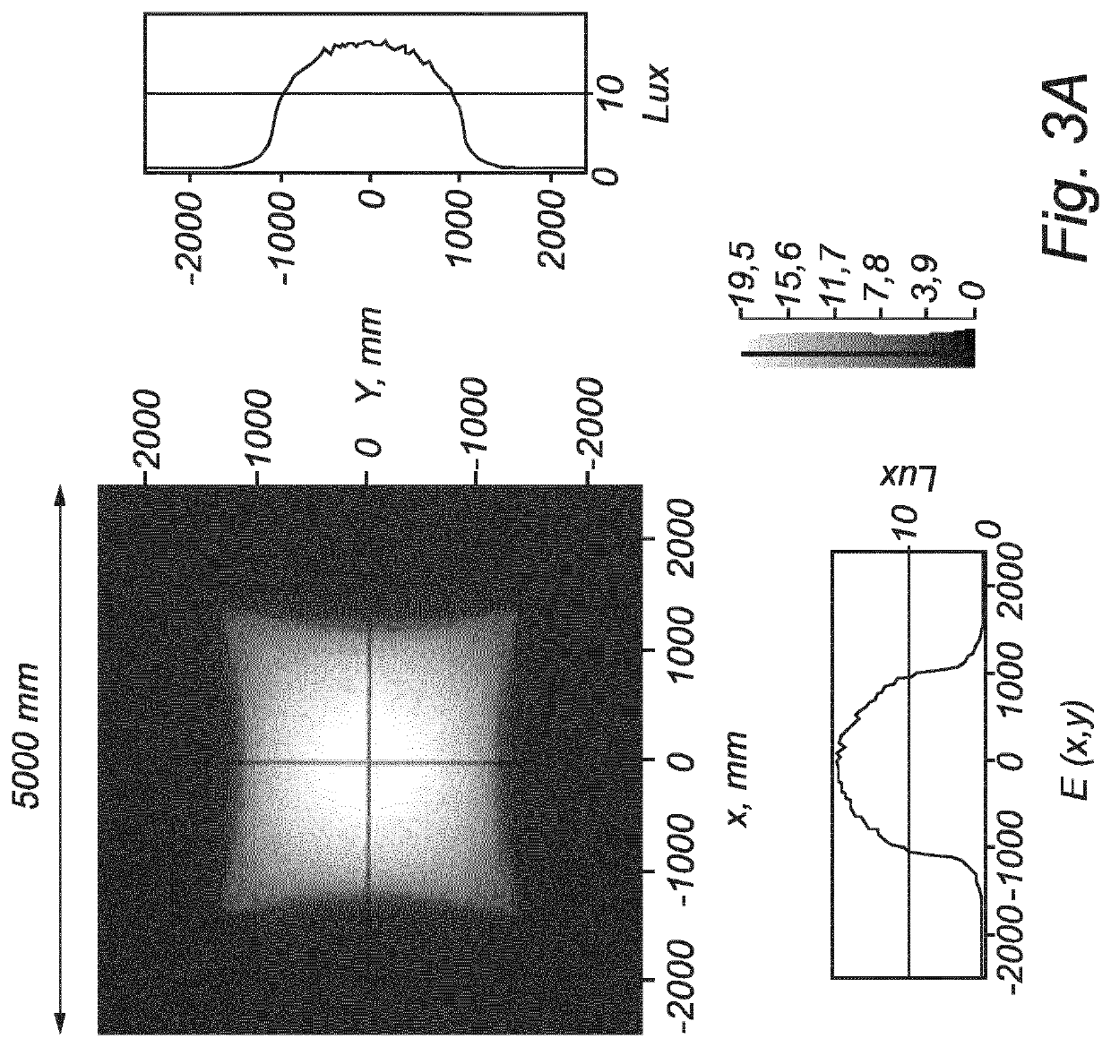
[0080]The reason for providing the light mixing chamber 400 of the light emitting device 100 with a square cross-sectional shape is to provide a square illuminated pattern. However, and as is illustrated on FIG. 3A, such a light mixing chamber 400 in fact provides a square light pattern with concave sides. FIG. 3B illustrates the intensity distribution of the pattern of FIG. 3A.
third embodiment
[0081]FIG. 4A shows cross-sectional side view of a light emitting device 101 according to the invention. FIG. 4B shows a bottom view of the light emitting device 101 according to FIG. 4A, and FIG. 4C shows a perspective view of a light mixing chamber 401 of the light emitting device 101 according to FIG. 4A. The light emitting device 101 differs from those of FIGS. 1-2C described above in that the light mixing chamber 401 of the light emitting device 101 is provided with a square cross-sectional shape with concave sides. The concave sides are provided since to obtain a perfect square illumination pattern, the shape of the light exit window 41 should be adapted in comparison with that shown in FIGS. 2A-C. The circumferential shape of the light exit window 41 of the light mixing chamber 401 could be defined by the following parametric equations:
x(t)=cos(t)2 / m*a*cos(t)cos(t){2}y(t)=sin(t)2 / m*a*sin(t)sin(t){3}
[0082]In equations 2 and 3, t is the parameter in the parametric repr...
PUM
 Abstract
Description
Claims
Application Information