Arrangement and a Method for measuring a Radar Cross Section

a technology of radar cross section and arrangement, applied in the direction of measuring devices, instruments, using reradiation, etc., can solve the problems of high investment and maintenance costs of a chamber to measure large objects such as real-size aircraft, and the effect of maintenance, and reducing the cost of operation

Pending Publication Date: 2022-08-11
AIRBUS DEFENCE & SPACE
View PDF0 Cites 0 Cited by
  • Summary
  • Abstract
  • Description
  • Claims
  • Application Information

AI Technical Summary

Benefits of technology

[0010]The main advantage of the invention is that it offers the possibility to measure the RCS of heavy and large targets with reduced, e.g. minimum, effort and cost. It also has a simple setup, not requiring any special preparation or modification of the object, since it can be located on the ground and not on a pylon.
[0011]The invention may also offer high-quality radar imaging, leading to a more detailed analysis of frequency dependence and the influence of single contributors. The invention may be modular and easy to transport and deploy in different locations for performing RCS measurements.
[0012]According to a first aspect, a method for measuring a Radar Cross Section (RCS) of an object is described. The method comprises acquiring, by an antenna, observations of the object by performing two dimensional near field frequency scans. The method further comprises computing, by a processor, the downrange profiles of the acquired observations. The method further comprises computing, by the processor, the three dimensional Inverse Synthetic Aperture Radar (ISAR) images by superimposing the downrange profiles. The method further comprises extracting, by the processor, the scattering centers of the object. The method further comprises computing, by the processor, the RCS of the object.
[0013]The method as a whole may enable the distortion produced by the antenna or antennas to be corrected. Furthermore, the methodology may allow for the mechanical deviation of the system to be corrected for during the scanning process. Additionally, the methodology may allow for the distortion introduced by the hardware gating to be corrected. Besides, the methodology may allow for filtering out the effects produced by the ground plane or any other reflective surface interacting with the object.
[0014]The first antenna may be one single antenna which is used for both transmitting and receiving, an antenna pair, wherein one antenna is used for transmitting and a second antenna is used for receiving, or an antenna array, wherein each antenna element can be selected for transmitting and / or receiving. Alternatively, instead of the first antenna, there may be an antenna pair or an antenna array. In some examples, an antenna array is used and an antenna pair within the antenna array is selected, wherein one antenna of the antenna pair is used for transmitting and a second antenna of the antenna pair is used for receiving.
[0015]The acquisition of the observations of the object by performing two dimensional near field frequency scans may allow for a detailed observation of the object. The two dimensional frequency scans may be undertaken by, preferably, an antenna pair or alternatively, an antenna, which may be displaced along the scanning surface. Alternatively, one dimension of the two dimensional near field frequency scans or both dimensions of the two dimensional near field frequency scans may be undertaken by switching between several antenna elements part of an antenna array. In the case of one dimension being scanned, the scanning of the other dimension may be undertaken by displacing the antenna array and then scanning the second dimension. This may avoid and / or reduce the displacement of the acquisition system and may reduce the acquisition time of the system. The results of the acquisition may be output to a processor located in the same location as the antenna. Alternatively, the processor may be located in a remote location. The results may be transferred to the processor via a wired connection and / or a wireless connection. In some embodiments, there may be multiple acquisitions of observations at a number of different locations.

Problems solved by technology

The RCS of air vehicles can be measured in-flight, however this results in expensive campaigns which do not offer accurate values.
However, the investment and maintaining costs of a chamber to measure large objects, such as a real-size aircraft, are extremely high.
The limitations of such arrangements are: the ground effect has to be mitigated, for example applying the patterning concept, and the target must be located on a pylon.
For other outdoor ranges, the main problem is the reflection from the ground surface.
These are not very practical solutions, and in many cases the target must be located on a pylon.
This requirement is the main disadvantage due to the complexity of this operation for large targets.
The main disadvantage is the required accuracy in the rotation which is difficult to fulfil with heavy targets.
In the case of a target of a physical size of ˜20 m, the distance must be in the order of tens of kilometers for X-band frequencies, introducing dramatic restrictions for the location of the facility.

Method used


Image

  • Arrangement and a Method for measuring a Radar Cross Section
  • Arrangement and a Method for measuring a Radar Cross Section
  • Arrangement and a Method for measuring a Radar Cross Section

Examples


Embodiment Construction

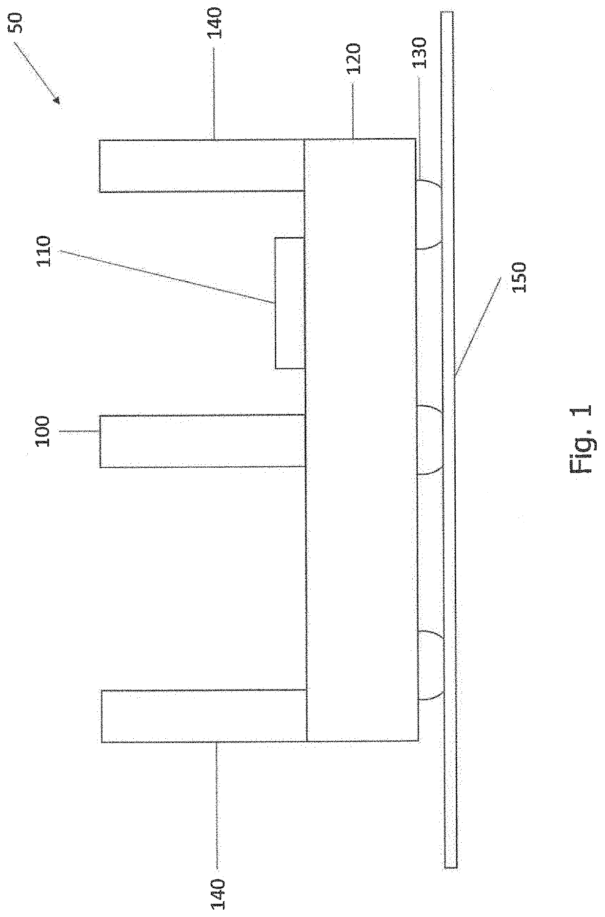
[0053]FIG. 1 shows a schematic diagram of the carrier and the components on and around the carrier according to an embodiment described herein.

[0054]In this example, the carrier assembly 50 comprises a first antenna 100, a housing 110 comprising the VNA and the HGE, the carrier 120 containing a motor, a plurality of wheels 130, two second antennas 140 and a rail 150. The first antenna 100 may alternatively be an antenna pair or an antenna array.

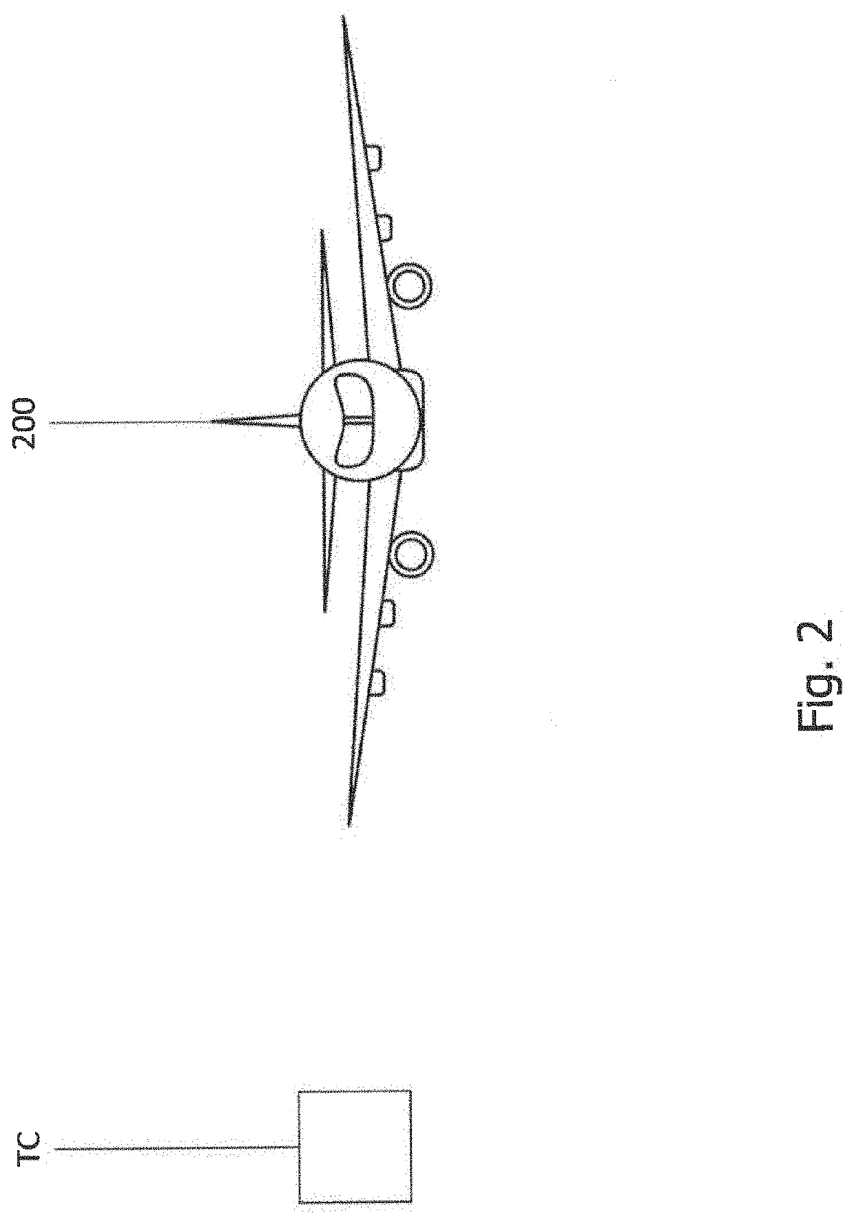
[0055]The first antenna 100 is a vertical array antenna which will be described in more detail below. The vertical array antenna allows for diversity to filter out the ground plane effects in the postprocessing which will also be described in more detail below. The first antenna 100 comprises a transmission unit and a receiving unit which transmits signals towards the object (see FIG. 2) for which the RCS is being measured and a receiving unit which receives the signals reflected from the object. Alternatively, these units can be combined int...


PUM


Abstract

A method for measuring a Radar Cross Section, RCS, of an object (200), wherein the method comprises: acquiring (S1000), by a first antenna (100), observations of the object (200) by performing two dimensional near field frequency scans; computing (S1100), by a processor, the downrange profiles of the acquired observations; computing (S1200), by the processor, the three dimensional Inverse Synthetic Aperture Radar, ISAR, images by superimposing the downrange profiles; extracting (S1300), by the processor, the scattering center of the object (200); and computing (S1400), by the processor, the RCS of the object (200).

Description

FIELD OF THE INVENTION[0001]The present invention relates to an arrangement and a methodology for measuring the Radar Cross Section (RCS) of targets / objects located on the ground. The measurement arrangement enables to filter out all the effects produced by the ground plane. The methodology enables to minimize the impact of the main sources of distortion inherent in the measurement arrangement.BACKGROUND TO THE INVENTION[0002]The RCS of air vehicles can be measured in-flight, however this results in expensive campaigns which do not offer accurate values. Indoor chambers, commonly referred as to anechoic chambers, do not present limitations due to ground interference. However, the investment and maintaining costs of a chamber to measure large objects, such as a real-size aircraft, are extremely high.[0003]Compact-range configurations, typically used in indoor facilities, can also be realized outdoors. The limitations of such arrangements are: the ground effect has to be mitigated, fo...

Claims


Application Information

Patent Timeline
Patent Type & Authority Applications(United States)
IPC IPC(8): G01S13/90G01S7/41
CPCG01S13/9064G01S7/411G01S7/40
Inventor GONZÁLEZ, JESÚS ÁLVAREZMEYERBRINGMANN, DIRKRITTER, JAN
Owner AIRBUS DEFENCE & SPACE
Why Eureka
Try Eureka