Auto-balancing hose system and method for fluid transfer

a hose system and hose technology, applied in the direction of liquid transferring devices, transportation and packaging, passenger handling devices, etc., can solve the problems of high stress around the riser base, damage to the hard arm, and high cost and maintenance of the arm, so as to achieve the effect of reducing the cost and maintenance, and easy inspection and replacemen

Active Publication Date: 2019-07-23
LIU XUEJIE
View PDF20 Cites 0 Cited by
  • Summary
  • Abstract
  • Description
  • Claims
  • Application Information

AI Technical Summary

Benefits of technology

[0013]The present invention provides an auto-balancing hose system for fluid transfer between an onshore facility and a vessel docked at a loading platform. The system comprises a transfer pipeline extended from the onshore facility to the loading platform and subjected to displacements relative to the loading platform, a hose with a first end fluidly connected to the transfer pipeline and a second end fluidly connected with a ship manifold (i.e., vessel manifold), a hose saddle or sheave that elevates the hose and divides the hose into a riser at the first end and a freely suspended U-tube next to the second end, and a counterweight or a winch with a predetermined pulling force that maintains a top tension to the riser. As a result, the entire hose is in tension. The hose is able to accommodate large ship motions, pipe end displacements and movements of the loading platform. When the loading platform sinks or slides down a slope due to soil consolidation, earthquakes or mudslides, the hose automatically adjusts its position without stressing the hose and the transfer pipeline.
[0019]It is another object of the invention to provide a loading system in which the hose can be easily inspected and replaced.
[0020]It is another object of the invention to provide a loading system with a minimum cost and maintenance.

Problems solved by technology

In reality, most hard arms are fixed at their base and the transfer pipeline is not allowed to expand and contract at the base of the arms.
Some hard arms have suffered damage due to thermal expansion of transfer pipelines and / or ground settlements of loading platforms.
In addition, these arms are costly and require maintenance with leakage potential at the swivel joints.
However, similar to the hard arm, the rigid riser is anchored at its base and any pipe expansion / contraction of the transfer pipeline or ground movement at the platform could cause high stress around the riser base.
However, this vertical shaft involves a different installation method rather than conventional piling and is likely to result in a higher construction cost for the cases where transfer pipelines are supported above the sea level.
Earthquakes, storm surges and soil erosions often trigger permanent ground deformations at a slope ground such as a coastal line or a river delta. The ground movements often overstress pipelines and / or loading systems.
Strengthening the slope around a coast or river bank is possible, but results in huge construction costs.
None of the systems mentioned above addresses the impact of permanent ground deformations that are likely to cause the movements of loading platforms.

Method used


Image

  • Auto-balancing hose system and method for fluid transfer
  • Auto-balancing hose system and method for fluid transfer
  • Auto-balancing hose system and method for fluid transfer

Examples


first embodiment

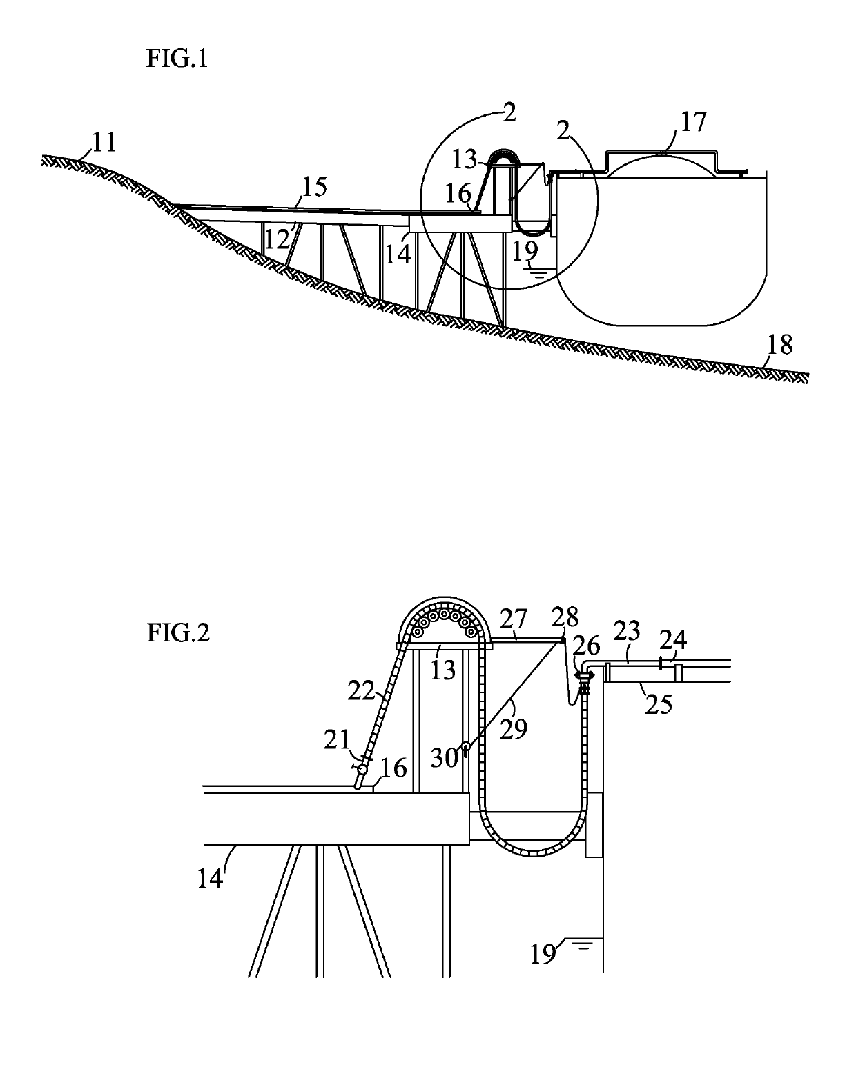
[0030]FIG. 1 is an overview of the present invention at a loading terminal. A vessel 17 is docked near a loading platform 14. A trestle 12 extends from a coastal area 11 (i.e., onshore area near the sea) to the loading platform 14, and supports a transfer pipeline 15 above the sea level 19 with a seabed 18 below. The transfer pipeline 15 is fluidly connected to an onshore facility (not shown). This onshore facility can be a storage tank, a temporary / mobile container, a fluid production plant (e.g., liquefied natural gas, chemical, biofuel, etc.), a pipeline network or a fluid consumer (e.g., a factory, a power plant, etc.). A hose saddle 13 is supported on the loading platform 14 and the transfer pipeline 15 ends below the hose saddle 13 with a free end 16. The transfer pipeline 15 is supported on low friction pads such as Teflon or on pipe rollers (not shown). This allows the pipeline to expand or contract axially at the free end 16. It also allows the loading platform to move away...

second embodiment

[0042]FIG. 7 shows this system. A floating storage vessel 71 is docked near a loading platform 14. A transfer pipeline 15 is elevated above the sea level 19, and preferably inclined with a high end at a coastal area 11 (refer to FIG. 1) and a low end at the loading platform 14. For cryogenic fluids or hot fluids, an insulation layer along with an external water barrier layer is required for the transfer pipeline 15. Alternatively, a transfer line can use a pipe-in-pipe configuration with insulation in the annulus.

[0043]Similarly, a hose 75 has a first end fluidly connected to the transfer pipeline 15 and a second end fluidly connected to a vessel manifold 24. Around a manifold platform 25, a manifold extension 72 extends from the vessel manifold 24, passes through a vertical support 73 and ends with a downward flange 74. The hose 75 is fluidly connected with the downward flange 74 at the second end. Alternatively, the second end of the hose 75 is directly connected to the vessel man...


PUM


Abstract

The present invention provides an auto-balancing hose system and a method for fluid transfer between an onshore facility and a floating vessel. The system comprises a transfer pipeline extended from the onshore facility to a loading platform, an upward pipe branch fluidly connected to the transfer pipeline, a hose with a first end fluidly connected to the upward pipe branch and a second end fluidly connected with a ship manifold on the floating vessel, a hose saddle or sheave that elevates the hose near the upward pipe branch and divides the hose into a riser at the first end and a U-tube next to the second end. The method includes elevating the hose near the upward pipe branch with a hose saddle and dividing the hose into a riser at the first end and a suspended U-tube at the second end. The hose is kept in tension, and adapted to accommodate vessel motions as well as relative displacements between the transfer pipeline and loading platform.

Description

CROSS-REFERENCE TO RELATED APPLICATIONS[0001]This application claims priority of U.S. Provisional Patent Application Ser. No. 62 / 317,533 filed on Apr. 2, 2016.U.S. Patent Documents[0002]3,434,491March 1969Bily137 / 3156,886,611May 2005Dupont et al141 / 2797,147,021December 2006Dupont et al141 / 3828,176,938May 2012Queau et al137 / 6158,915,271December 2014Liu141 / 382STATEMENT REGARDING FEDERALLY SPONSORED RESEARCH OR DEVELOPMENT[0003]Not ApplicableBACKGROUND OF THE INVENTION1. Field of Invention[0004]The present invention relates generally to transferring fluids between an onshore facility and a floating vessel. Specifically, the present invention provides an auto-balancing hose system that accommodates vessel motions as well as relative displacements between a transfer pipeline and a loading platform.2. Description of the Related Art[0005]Ships move goods and commodities from shore to shore. In some cases, a vessel is docked near shore and serves as a storage unit or production unit. Fluids...

Claims


Application Information

Patent Timeline
Patent Type & Authority Patents(United States)
IPC IPC(8): B67D9/00B65H75/36B65H57/14B63B27/34
CPCB67D9/00B65H57/14B65H75/366B65H2701/33B63B27/34
Inventor LIU, XUEJIE
Owner LIU XUEJIE
Why Eureka
Try Eureka