
Process for selective isolation of CFRP parts by electrodeposition coatings

a technology of electrodeposition coating and cfrp, which is applied in the direction of fluid pressure measurement, liquid/fluent solid measurement, peptide, etc., can solve the problems of rusting of metal, large time and labor, and defects on the surface, so as to reduce the material used for repairing, reduce manufacturing efforts and costs, and facilitate selective repairing. , the effect of reducing the number of defects

Active Publication Date: 2014-06-05
AIRBUS OPERATIONS GMBH
View PDF1 Cites 0 Cited by
  • Summary
  • Abstract
  • Description
  • Claims
  • Application Information

AI Technical Summary

Benefits of technology

The invention aims to improve the corrosion protection of CFRP hybrid structures while minimizing costs and weight. It allows for easy automation and repairing of defects, reducing manufacturing efforts and workforce requirements. Overall, the invention improves the durability and reliability of CFRP structures.

Problems solved by technology

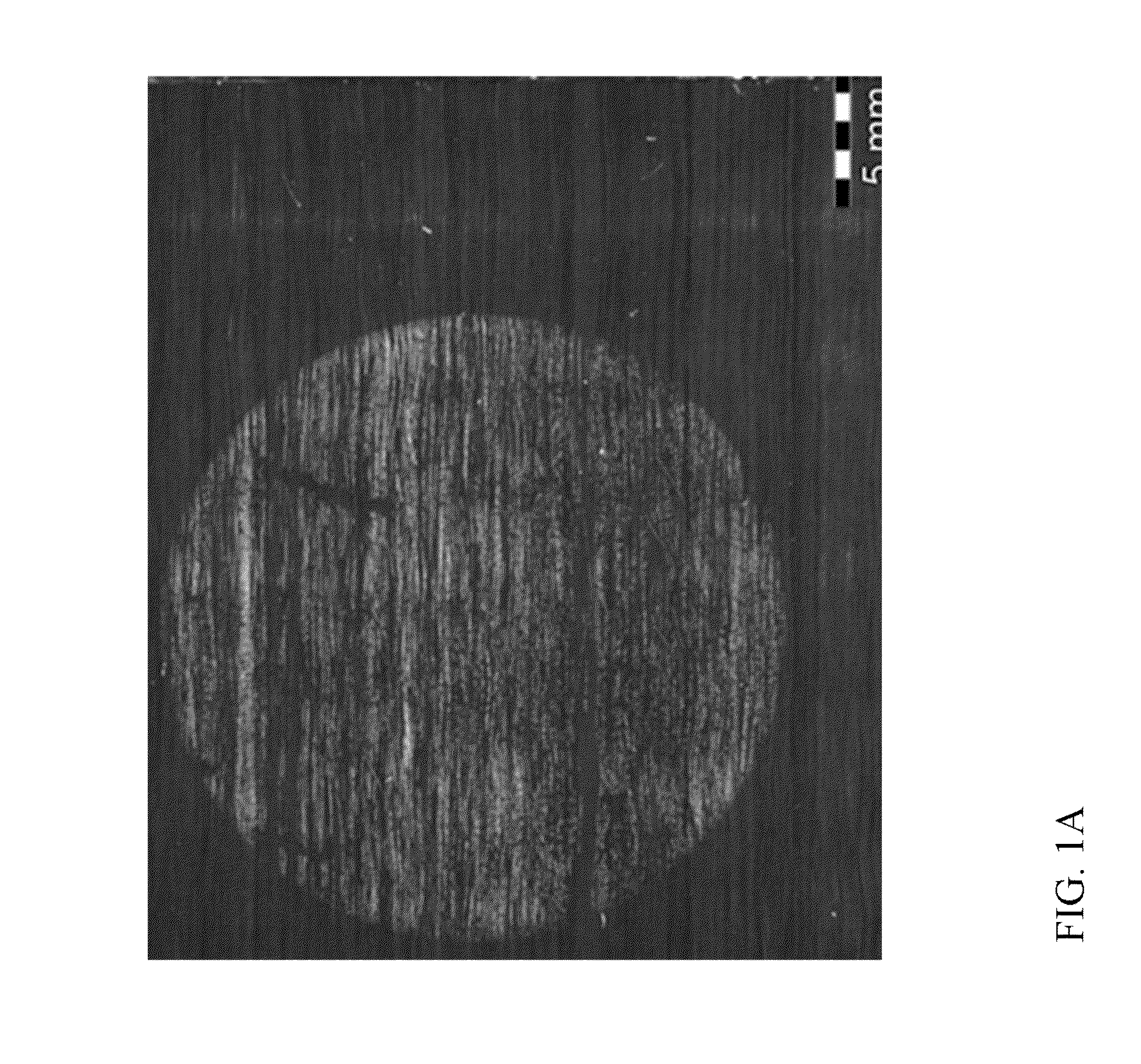
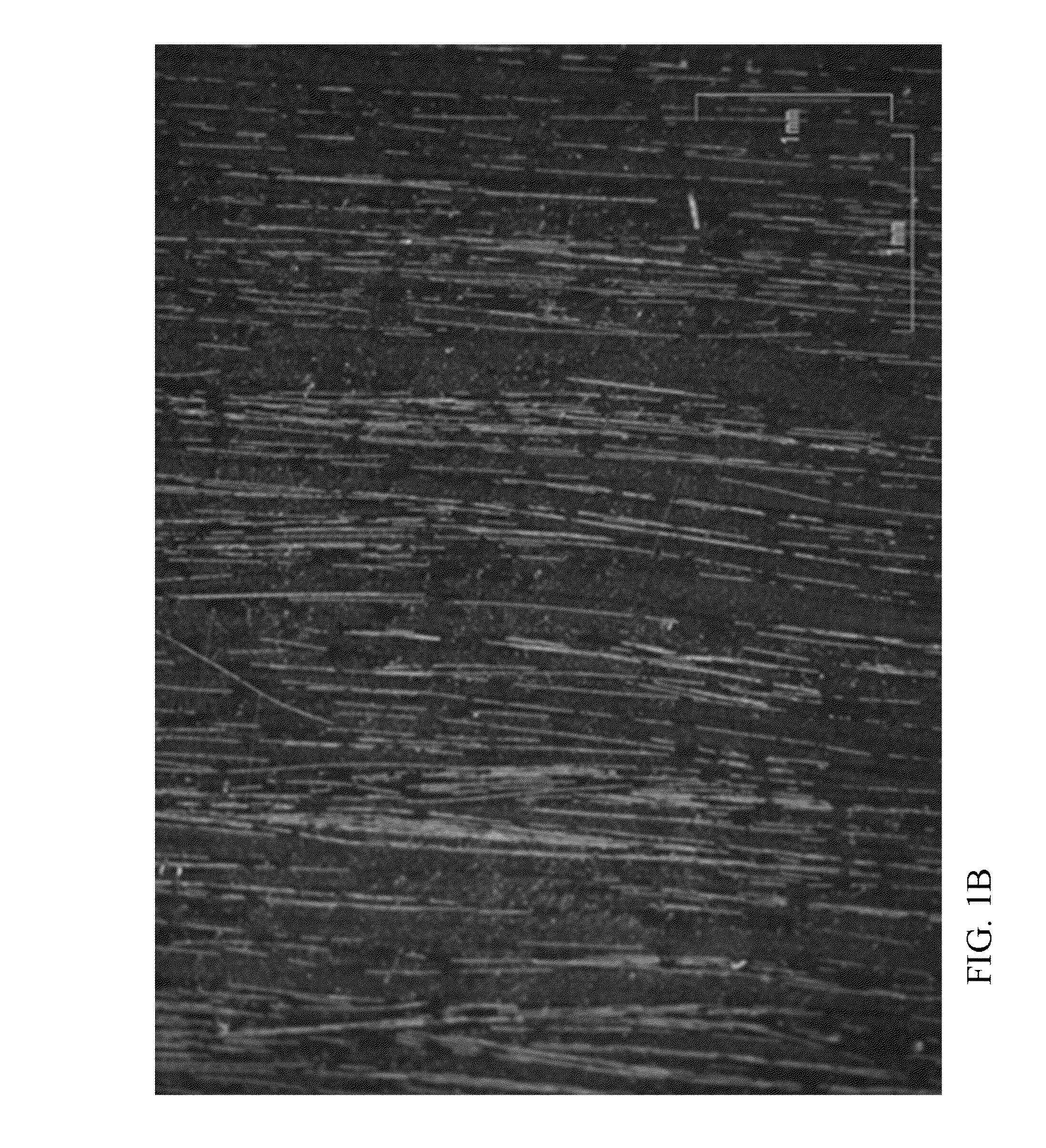
However, during these further treatments or already during the production of the CFRP components normally defects occur on the surface thereof, e.g., places where carbon fibers are at least partially exposed to the surroundings.
If such places with defects are then bound to a metal in a hybrid structure in e.g., airplanes, cars, bikes, etc. and water is present or gets to the binding location between an exposed carbon fiber part and the metal, a galvanic cell may be formed, which may lead to rusting of the metal due to the reduction of oxygen on the carbon fiber.
Conventionally this repairing of defects is either carried out manually, which requires a lot of time and labor and is thus time- and cost-extensive, or is done by extensive application of isolating glass plies, resin layers or coatings, using e.g., epoxy resin or polyurethane resin, which is costly and requires a significant amount of material.
However, also such treatment leads to an increase in weight of the CFRP component and thus is not advantageous, especially in light-weight applications.

Method used


Image

  • Process for selective isolation of CFRP parts by electrodeposition coatings
  • Process for selective isolation of CFRP parts by electrodeposition coatings
  • Process for selective isolation of CFRP parts by electrodeposition coatings

Examples


example 1

[0046]CFRP components of a material comprising Fibredux 913C-815 with a resin content of 35-40% by volume was treated with peel ply and wet-ground.

[0047]These components were then treated either by anaphoretic electrodeposition or cathaphoretic electrodeposition under the following conditions to check for the influence of several parameters on the coating result:

[0048]Cathaphoretic deposition:

[0049]Resin: acryl-based resin of ICI company

[0050]Temperature: 20° C.-40° C.

[0051]Voltage: 100 V-180 V

[0052]Duration: 0.5 minutes- 2 minutes

[0053]Anaphoretic deposition:

[0054]Resin: polyester-melamine-based resin of Herberts company

[0055]Temperature: 25° C. + / −2° C.

[0056]Voltage: 130 V-170 V

[0057]Duration: 0.5 minutes-2 minutes

[0058]Under all conditions a satisfactory repairing and insulation of surface defects could be achieved.

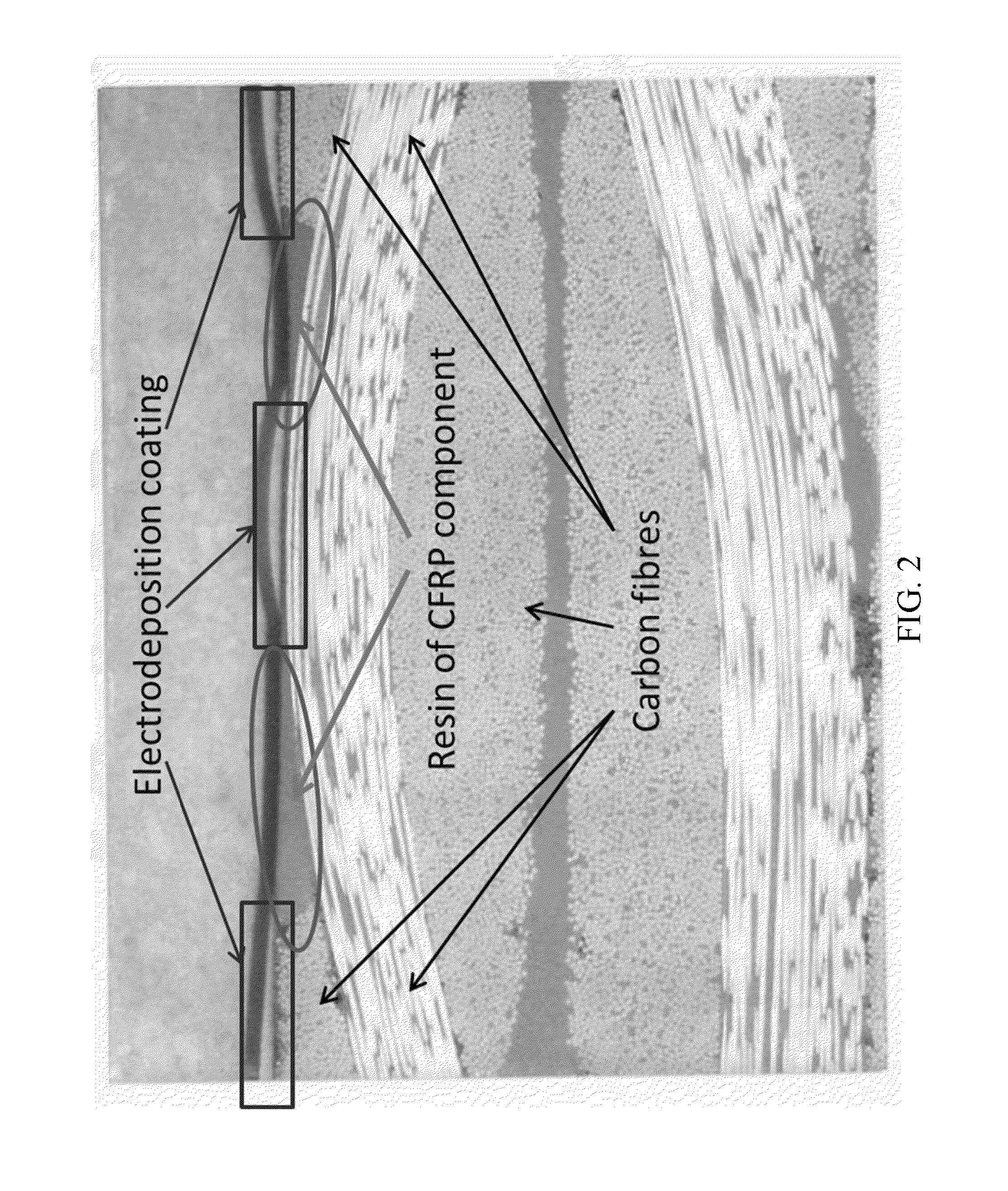
[0059]An exemplary repairing of a CFRP component with anaphoretic deposition using the polyester-melamine-based resin can be seen in FIG. 2. FIG. 2 shows a CFRP compon...

example 2

[0061]Various CFRP components with various compositions were cleaned with a solvent after the initial treatment, and an electrodeposition coating was carried out with ATL Aerocron™ of PPG company at a temperature of 25° C. at voltages of 90 V-210 V for 2 minutes, with a ramp in the first 30 seconds and a constant voltage for 90 seconds.

[0062]As in example 1 under all conditions a satisfactory repairing and insulation of surface defects could be achieved.


PUM

PropertyMeasurementUnit
Temperatureaaaaaaaaaa
Electric potential / voltageaaaaaaaaaa

Abstract

A process of repairing defects on a carbon fiber reinforced plastic (CFRP) component wherein defects on a surface of a CFRP component are selectively repaired by electrodeposition coating. With this process a reduction of coating material and work force as well as weight of the repaired CFRP component can be achieved.

Description

CROSS-REFERENCES TO RELATED APPLICATIONS[0001]This application claims the benefit of the U.S. Provisional Application No. 61 / 674,898, filed on Jul. 24, 2012, and of the European patent application No. 12 177 698.3 filed on Jul. 24, 2012, the entire disclosures of which are incorporated herein by way of reference.FIELD OF THE INVENTION[0002]The present invention relates to a process of repairing defects on a carbon fiber reinforced plastic (CFRP) component wherein defects on a surface of a CFRP component are selectively repaired by electrodeposition coating using an insulating coating material.BACKGROUND OF THE INVENTION[0003]Carbon fiber reinforced plastic (CFRP) components are nowadays used in many industrial fields, e.g., in the aeronautic and automobile industry, as they enable a significant weight reduction compared to previously used metal parts and provide sufficient stability and therefore safety for the user.[0004]During production of CFRP components carbon fibers are suspen...

Claims


Application Information

Patent Timeline
IPC IPC(8): C25D13/00
CPCC25D13/00B29C73/00C25D13/12C09D5/44C25D5/02
Inventor KOTT, ROUVENFANGMEIER, ARMINSCHROEDER, SIMONELEMCKAU, THOMAS
Owner AIRBUS OPERATIONS GMBH
Learn More