Electronic monitoring circuit for detecting the variation in the power or current absorbed by at least one electronic circuit under test and electronic system for testing the operation of the at least one electronic circuit

a technology of electronic circuit and electronic monitoring circuit, which is applied in the direction of power measurement through pulse modulation, measurement instrument housing, instruments, etc., can solve the problems of increasing system complexity, space occupation, and occupying a small spa

Pending Publication Date: 2022-08-18
ELDOR CORP SPA
View PDF4 Cites 0 Cited by
  • Summary
  • Abstract
  • Description
  • Claims
  • Application Information

AI Technical Summary

Benefits of technology

The present invention provides an electronic monitoring circuit that uses a simple and space-saving circuit to test electronic circuits. It reuses the pulse-width modulation control signal that is already present in the switch mode power supply supplying the test circuit. This circuit does not require the use of current reading resistors, which could change the system design parameters. This results in an improved design that is cost-effective and efficient.

Problems solved by technology

The Applicant has observed that this known technique has the disadvantage of requiring the use of dedicated circuits for each part of the circuit under test, thus increasing the space occupancy, complexity and cost of the system.

Method used


Image

  • Electronic monitoring circuit for detecting the variation in the power or current absorbed by at least one electronic circuit under test and electronic system for testing the operation of the at least one electronic circuit
  • Electronic monitoring circuit for detecting the variation in the power or current absorbed by at least one electronic circuit under test and electronic system for testing the operation of the at least one electronic circuit
  • Electronic monitoring circuit for detecting the variation in the power or current absorbed by at least one electronic circuit under test and electronic system for testing the operation of the at least one electronic circuit

Examples


Embodiment Construction

[0025]It should be observed that in the following description, identical or analogous blocks, components or modules are indicated in the figures with the same numerical references, even where they are illustrated in different embodiments of the invention.

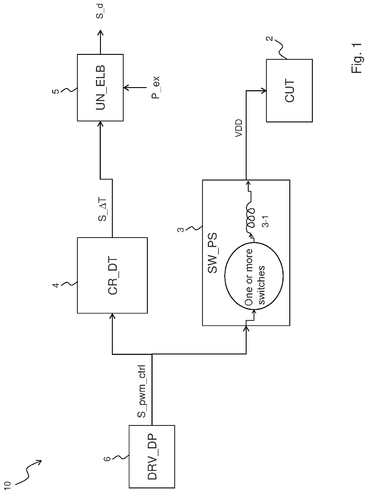
[0026]Referring to FIG. 1, it shows a block diagram of an electronic system 10 for testing the operation of an electronic circuit 2 according to the invention, in which said test is performed in an operating condition of the electronic circuit 2 which is defined (i.e., a known operating condition).

[0027]For example, the test of the operation of the electronic circuit 2 under test is carried out when the electronic circuit 2 under test is activated, i.e., when it switches from a condition in which it is not powered to a condition in which it is powered (e.g., in the automotive field when the motor vehicle is switched on after a condition in which it is switched off).

[0028]Note that more generally the invention is applicable to the te...


PUM


Abstract

An electronic monitoring circuit for detecting a variation in the power or current absorbed by an electronic circuit under test is disclosed. The circuit includes an input terminal adapted to receive a pulse-width modulation control signal, a resistor having a first terminal connected to the input terminal, and a capacitor having a first terminal connected to a second terminal of the resistor. The output terminal is adapted to generate an output signal as a function of the value of the voltage drop at the ends of the capacitor, said output signal being representative of a variation of the pulse width of the pulse-width modulation control signal. The variation of the pulse width is a function of the power or current absorbed by the electronic circuit under test.

Description

TECHNICAL FIELD OF THE INVENTION[0001]The present invention generally relates to the field of testing and diagnostics of the operation of electronic devices, for example in the automotive field.[0002]More in particular, the present invention concerns an electronic monitoring circuit for detecting the variation in the power or current absorbed by one or more electronic devices under test and relates to an electronic system for testing the correct operation of the one or more electronic devices by means of said detection of the variation in the power or current absorbed by the one or more electronic devices.PRIOR ART[0003]In the automotive sector it is important to carry out diagnostics of electronic circuits during their normal operation in order to verify their correct operation.[0004]This is done by inserting several dedicated circuits that are able to detect only the presence of short circuits or if components or electronic circuits are present which are switched off.[0005]The App...

Claims


Application Information

Patent Timeline
Patent Type & Authority Applications(United States)
IPC IPC(8): G01R31/28G01R21/07G01R1/04
CPCG01R31/282G01R1/0416G01R21/07G01R19/0092G01R21/127H02M3/156H02J7/0063H02J2207/20
Inventor SCARAMUCCI, CIROSILVESTRI, GIOVANNIFORTE, PASQUALE
Owner ELDOR CORP SPA
Why Eureka
Try Eureka