Unlock instant, AI-driven research and patent intelligence for your innovation.

Dynamic Pinhole Aperture for Charged Particle Therapy Systems

a technology of charged particle and pinhole aperture, which is applied in the field of dynamic pinhole aperture assembly, can solve the problems of poor protection of nearby oars, enlarge the dose penumbra, and the lowest energy availabl

Pending Publication Date: 2022-08-25
MAYO FOUND FOR MEDICAL EDUCATION & RES
View PDF0 Cites 0 Cited by
  • Summary
  • Abstract
  • Description
  • Claims
  • Application Information

AI Technical Summary

Benefits of technology

The patent is for a device that can control the size of a hole through which charged particles can pass. It is made up of a plate and a stage that can move the plate in different directions. The device has two main advantages: it can make the hole smaller in size, and it can make the hole larger in size. This makes it easier to control the movement of particles through the device.

Problems solved by technology

Due to the limitation of the lowest energy available from the accelerator, range shifters—which usually are placed upstream in the beamline—have to be used to treat shallow tumors.
Unfortunately, the introduction of range shifters significantly increases the spot sizes, which in turn enlarges the dose penumbra greatly and results in poor protection of nearby OARs.
This issue is especially severe in head and neck (HN) cancer treatment, where tumors are usually shallow and where the number and proximity of OARs (e.g., brainstem and optic-nerve structures) are more pronounced.
Even with these methods, the spot sizes can still be too large, and therefore clinically acceptable SSPT plans cannot be generated, yet.
In such scenarios, the protection of adjacent OARs, such as brainstem or optic nerve structures, has to be compromised, which results in undesired patient outcomes.
The static aperture only reduces the dose outside the largest cross section, which limits its effectiveness in some cases.
Static apertures have also been suggested for use in SSPT; however, patient-specific static apertures are expensive and time consuming to produce, which makes adaptive re-planning somewhat prohibitive.
The use of MLCs in proton therapy has been investigated; however, their use has been limited since they would need to span a large area and are quite mechanically complex.

Method used


Image

  • Dynamic Pinhole Aperture for Charged Particle Therapy Systems
  • Dynamic Pinhole Aperture for Charged Particle Therapy Systems

Examples


Embodiment Construction

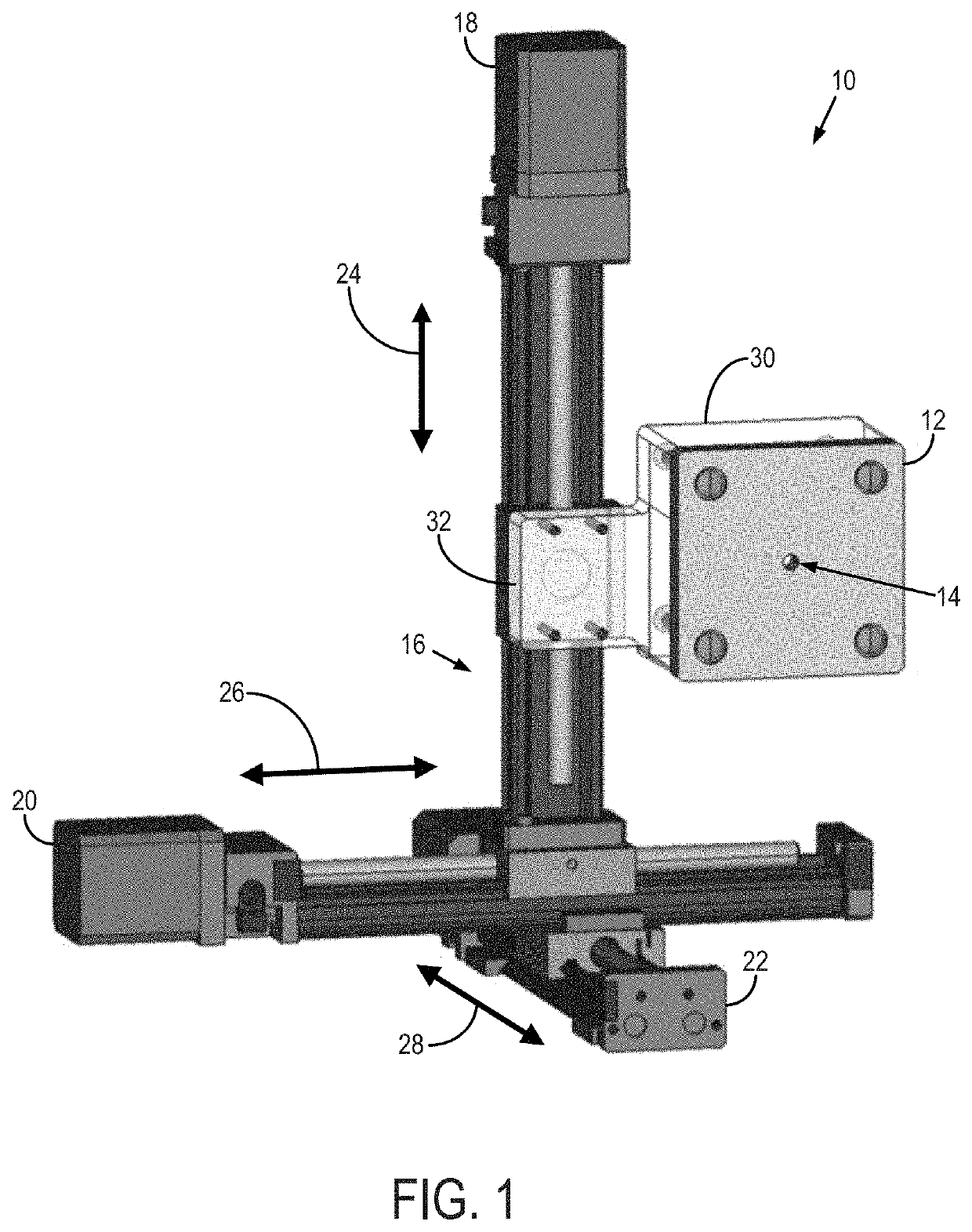
[0011]Described here is a dynamic pinhole aperture for use with radiation therapy systems, such as photon therapy systems (e.g., intensity-modulated x-ray based radiation therapy systems) and charged particle therapy systems, which can include proton therapy systems, heavy ion (e.g., carbon) therapy systems, and the like. In general, the dynamic pinhole aperture includes a small and mobile pinhole aperture, which in some configurations may have a range shifter coupled thereto. The dynamic pinhole aperture is a simple and low-cost dynamic collimator that is designed to be movable with the beam during irradiation, which allows for reducing the size of each discrete spot and, therefore, the target dose penumbra. In some instances, the dynamic pinhole aperture can be referred to as a spot-scanning aperture as it enables scanning a spot-scanning of the radiation therapy beam. Thus, better critical organ protection with only a slight increase of beam-on time can be achieved simultaneously...


PUM


Abstract

A dynamic pinhole aperture is configured for use with charged particle therapy systems, such as proton therapy systems. In general, the dynamic pinhole aperture includes a small and mobile pinhole aperture. The dynamic pinhole aperture is designed to be movable with the beam during irradiation, which allows for reducing the size of each discrete spot and, therefore, the target dose penumbra. The dynamic pinhole aperture is carefully designed to balance the reduction of spot sizes (thus target dose penumbra) and the reduction of beam transmission ratios, which allows for the device to be used clinically to treat large tumors.

Description

CROSS-REFERENCE TO RELATED APPLICATIONS[0001]This application claims the benefit of U.S. Provisional Patent Application Ser. No. 63 / 147,401, filed on Feb. 9, 2021, and entitled “DYNAMIC PINHOLE APERTURE FOR CHARGED PARTICLE THERAPY SYSTEMS,” which is herein incorporated by reference in its entirety.BACKGROUND[0002]Spot scanning proton therapy (SSPT) uses magnetic steering of a narrow proton beam, termed a beamlet, to deliver a dose to a spot inside the patient. SSPT allows for significant flexibility in dose delivery, enabling treatment optimization methods that were previously not permissible. As a result, SSPT offers improved high-dose conformity when compared with passive scattering proton therapy (PSPT) and offers better sparing of organs-at-risk (OARs) in the mid-dose to low-dose range when compared to intensity-modulated x-ray-based therapy.[0003]The conformity of the dose distribution is characterized by the dose penumbra, which is highly related to the spot size. The new gen...

Claims


Application Information

Patent Timeline
IPC IPC(8): G21K1/02A61N5/10G21K5/04
CPCG21K1/02A61N5/1077G21K5/04A61N2005/1087A61N2005/1095A61N5/1043
Inventor HOLMES, JASON M.LIU, WEI
Owner MAYO FOUND FOR MEDICAL EDUCATION & RES