
Travel cycle for a condenser or heat pump dryer appliance

a technology of condenser dryer and travel cycle, which is applied in the field of drying appliances, can solve the problems of excessive wear and premature failure of appliance components, damage to the appliance, the installation area, the transport vehicle, etc., and achieves the effect of avoiding the wear and tear of the appliance, avoiding the occurrence of abrasion and affecting the service life of the appliance, and avoiding the occurrence of abrasion and abrasion

Pending Publication Date: 2022-09-22
HAIER US APPLIANCE SOLUTIONS INC
View PDF0 Cites 0 Cited by
  • Summary
  • Abstract
  • Description
  • Claims
  • Application Information

AI Technical Summary

Benefits of technology

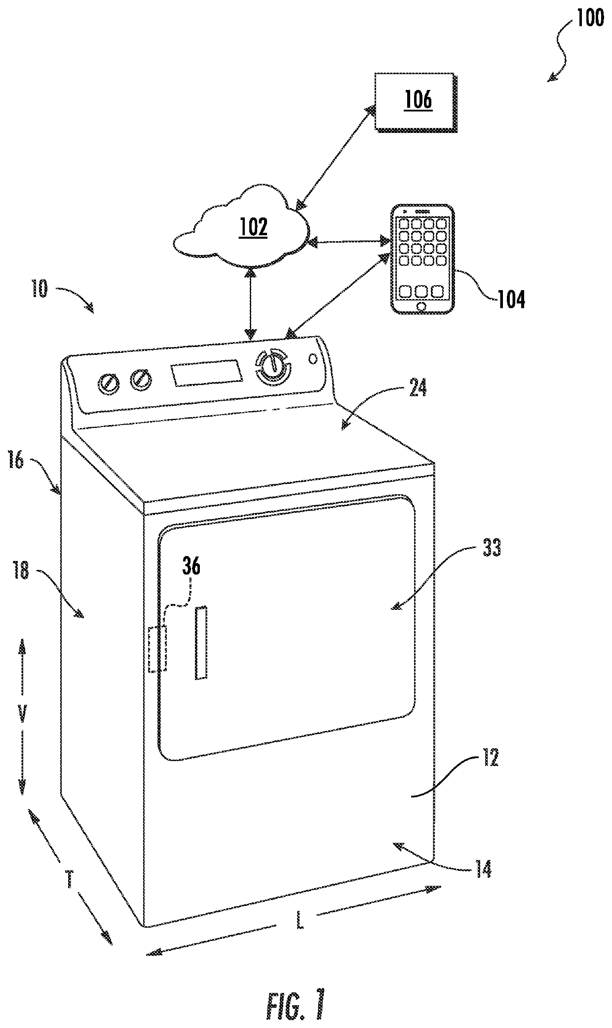
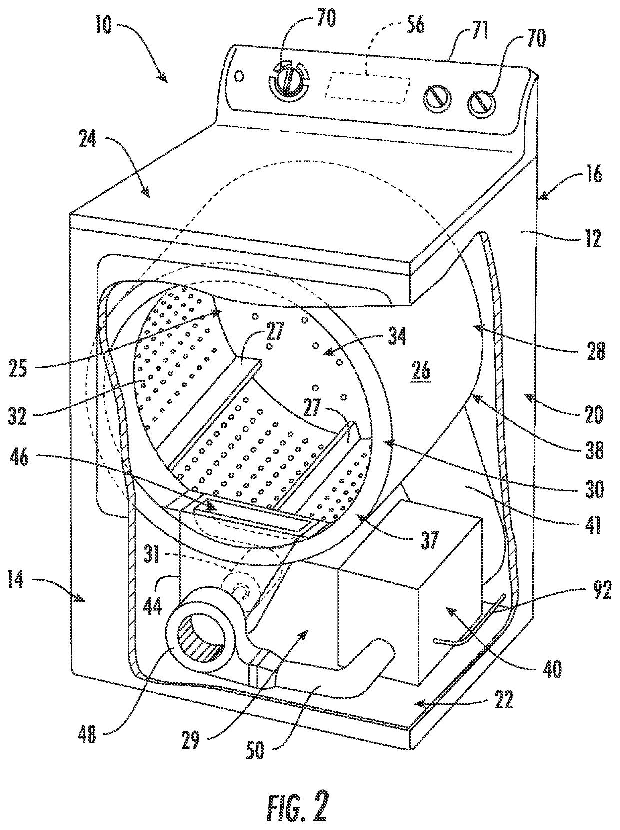
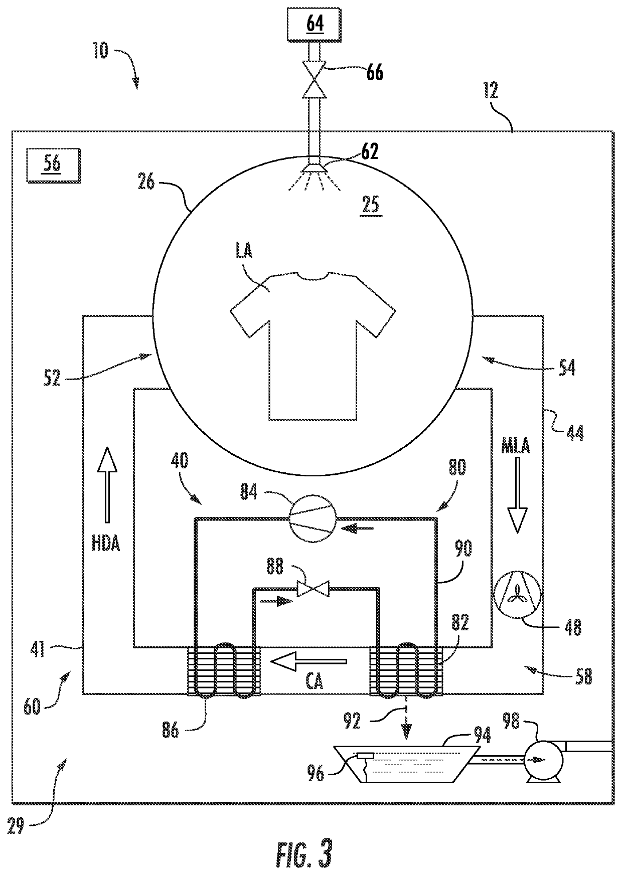
The present invention is about a dryer appliance and a method of operating it. The appliance includes a drum with a chamber for drying articles, a conditioning system for heating and removing moisture from air, a duct system for connecting the conditioning system to the drum, a blower fan for moving air through the process, and a controller for controlling the appliance's operation. The method includes receiving a command to initiate a travel cycle and preparing the appliance for travel. The invention allows for efficient and effective drying of articles even when the appliance is being moved around.

Problems solved by technology

However, laundry appliances may periodically need to be moved or transported from one location to another.
Notably, such appliance transport may cause damage to the appliance, the transport vehicle, the installation area, and / or external objects if preventative measures are not taken.
For example, moving internal components of the appliance may experience forces not associated with normal operation, resulting in the potential for excessive wear and premature failure of appliance components.
In addition, fluids in the appliance can leak, doors may swing freely, and mold or mildew may form if the drum is not properly drained and dried prior to transport.

Method used


Image

  • Travel cycle for a condenser or heat pump dryer appliance
  • Travel cycle for a condenser or heat pump dryer appliance
  • Travel cycle for a condenser or heat pump dryer appliance

Examples


Embodiment Construction

[0015]Reference now will be made in detail to embodiments of the invention, one or more examples of which are illustrated in the drawings. Each example is provided by way of explanation of the invention, not limitation of the invention. In fact, it will be apparent to those skilled in the art that various modifications and variations can be made in the present invention without departing from the scope or spirit of the invention. For instance, features illustrated or described as part of one embodiment can be used with another embodiment to yield a still further embodiment. Thus, it is intended that the present invention covers such modifications and variations as come within the scope of the appended claims and their equivalents.

[0016]As used herein, the terms “first,”“second,” and “third” may be used interchangeably to distinguish one component from another and are not intended to signify location or importance of the individual components. The terms “includes” and “including” are...


PUM


Abstract

A dryer appliance and a method of operating the same are provided. In one aspect, the dryer appliance includes a drum rotatably mounted within a cabinet. The drum defines a chamber that is in fluid communication with a conditioning system of the dryer appliance that circulates heated air through the chamber. A controller is configured to receive a command to initiate an appliance travel cycle and implement a responsive action to prepare the dryer appliance for travel. The responsive action may be the automated adjustment of one or more operating parameters of the dryer appliance, such as performing a load sensing procedure, drying the chamber, closing the water supply valves, etc. In addition, the responsive action may include providing a user instruction to prepare the dryer appliance, e.g., by cleaning the lint filter, emptying the condensate collection tank, removing hoses and cables, addressing any error codes, etc.

Description

FIELD OF THE INVENTION[0001]The present subject matter relates generally to dryer appliances, or more specifically, to systems and methods for preparing a heat pump or condenser dryer appliance for movement or travel.BACKGROUND OF THE INVENTION[0002]Laundry appliances are commonly installed in fixed locations, e.g., in a laundry room, where they are securely grounded during operation. These stable locations provide for safe operation of the appliances and their many moving parts. For example, dryer appliances are designed to absorb or handle moderate forces associated with the movement of such components during normal operation while the dryer appliance is stable and stationary. However, laundry appliances may periodically need to be moved or transported from one location to another. For example, these appliances may be transferred between properties when the consumer moves between homes. In mobile appliance installations, such as in recreational vehicles, movement or transport of t...

Claims


Application Information

Patent Timeline
Patent Type & Authority Applications(United States)
IPC IPC(8): D06F58/34D06F34/18D06F34/20D06F58/24D06F34/28D06F34/04
CPCD06F58/34D06F34/18D06F34/20D06F58/24D06F34/28D06F34/04D06F2103/04D06F58/32D06F2103/40D06F2105/02D06F2105/54D06F2105/58D06F2105/36D06F2105/08D06F2103/42D06F2103/58D06F39/001
Inventor EKBUNDIT, MICHAEL WUTTIKORN
Owner HAIER US APPLIANCE SOLUTIONS INC
Learn More