
Stereoscopic display device

a stereoscopic display and display screen technology, applied in optics, instruments, electrical appliances, etc., can solve the problems of reducing the effect of stereoscopic display, the difficulty of separating the left-right disparity image and the right-right disparity image, etc., to improve the stereoscopic display effect in the edge region, and reduce crosstalk between images

Inactive Publication Date: 2022-09-22
ACER INC
View PDF6 Cites 0 Cited by
  • Summary
  • Abstract
  • Description
  • Claims
  • Application Information

AI Technical Summary

Benefits of technology

The patent describes a type of display that shows 3D images. This display has a special lens that helps create a more accurate and realistic picture for the viewer. By adjusting the curvature of the lens, the display can show different images to each eye, reducing the interference between them. This results in a better 3D display effect, especially in the edges of the display.

Problems solved by technology

However, when an angle of view is large, crosstalk exists between the left disparity image and the right disparity image, so that it is difficult to separate the left right disparity image and the right disparity image, and the effect of the stereoscopic display is thus reduced.

Method used


Image

  • Stereoscopic display device
  • Stereoscopic display device
  • Stereoscopic display device

Examples


Embodiment Construction

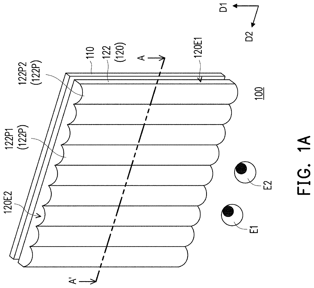
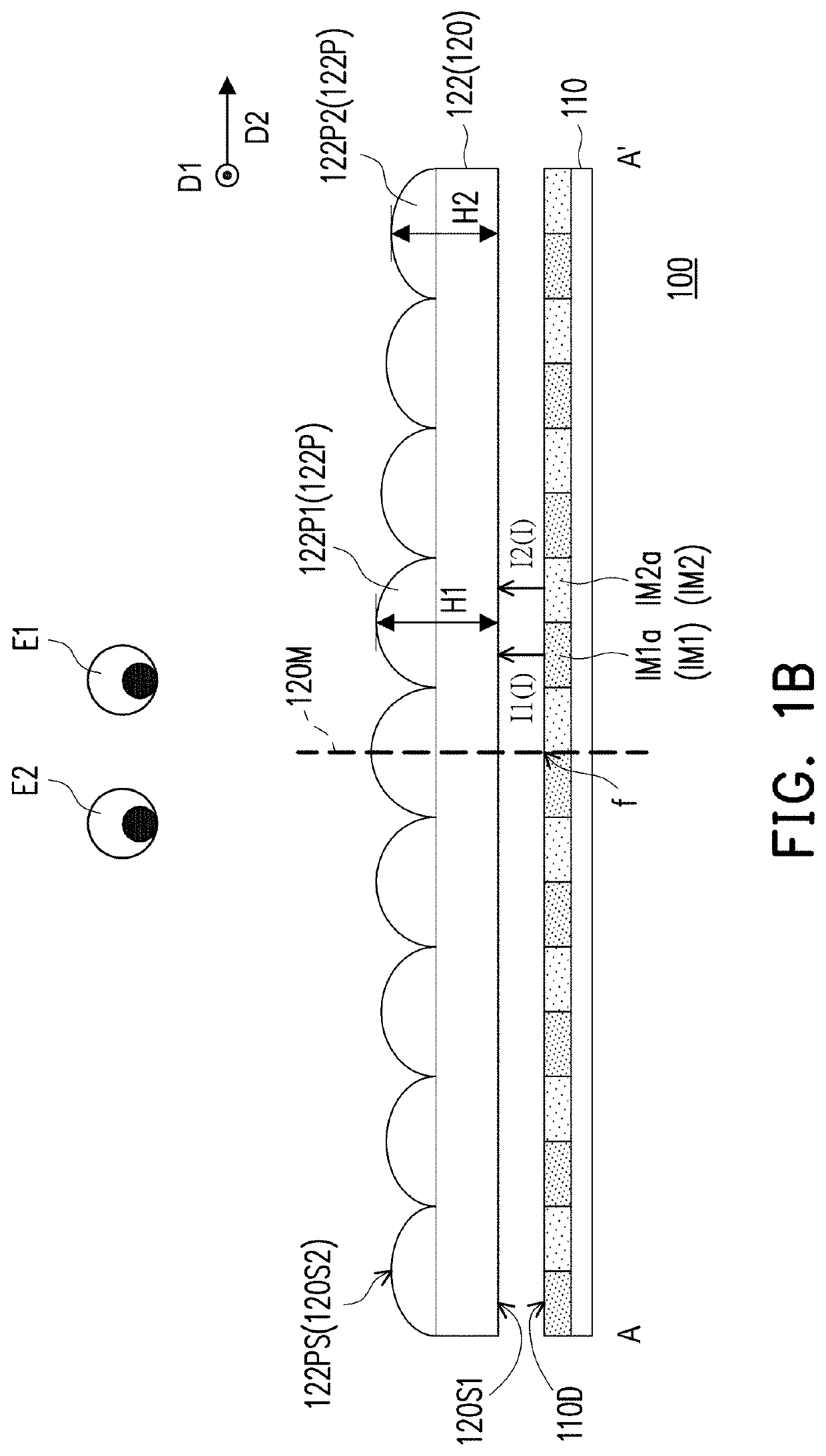
[0013]FIG. 1A is a perspective diagram of a stereoscopic display device according to an embodiment of the disclosure. FIG. 1B is a schematic cross-sectional diagram of the stereoscopic display device in FIG. 1A. FIG. 1B is a schematic cross-sectional diagram of a stereoscopic display device 100 in FIG. 1A along a section line A-A′. Referring to FIGS. 1A and 1B, the stereoscopic display device 100 according to the embodiment includes a display panel 110 and an optical element 120. The display panel 110 may be a liquid crystal display panel, a light emitting diode display panel, an organic light emitting diode display panel, or other types of display panels, and the disclosure is not limited thereto.

[0014]The optical element 120 is disposed on a display surface 110D of the display panel 110. The display panel 110 may emit an image beam I from the display surface 110D. The image beam I penetrates the optical element 120 and enters eyes E1 and E2 of a user to present a stereoscopic imag...


PUM


Abstract

A stereoscopic display device including a display panel and an optical element is provided. The optical element is disposed on a display surface of the display panel. The optical element includes a lenticular lens array. The lenticular lens array includes a plurality of lenticular lenses extending in a first direction. The lenticular lenses are arranged in a second direction. The optical element includes a center line extending in the first direction. The lenticular lenses include a first lenticular lens and a second lenticular lens. The distance between the first lenticular lens and the center line is smaller than the distance between the second lenticular lens and the center line, and the curvature of the first lenticular lens is greater than the curvature of the second lenticular lens.

Description

CROSS-REFERENCE TO RELATED APPLICATION[0001]This application claims the priority benefit of Taiwan application serial no. 110110200, filed on Mar. 22, 2021. The entirety of the above-mentioned patent application is hereby incorporated by reference herein and made a part of this specification.BACKGROUNDTechnical Field[0002]The disclosure relates to a display device, and in particular to a stereoscopic display device.Description of Related Art[0003]Currently, a stereoscopic image can be presented by using different methods. Generally, stereoscopic image display devices can be categorized into stereoscopic displays that need to be used with glasses and naked-eye stereoscopic displays. In a naked-eye stereoscopic display, an optical element, such as a disparity grating or a biconvex lens, may be installed at the front part of a display screen to separate optical axes of a left disparity image and a right disparity image. However, when an angle of view is large, crosstalk exists between ...

Claims


Application Information

Patent Timeline
IPC IPC(8): G02B30/27G02B3/00G02B30/22
CPCG02B30/27G02B3/0006G02B30/22G02B30/29H04N13/305
Inventor CHIU, YI-JUNGHUANG, SHIH-TINGLI, YEN-HSIENTU, TSUNG-WEISHIH, WEI-KUO
Owner ACER INC
Features
  • Generate Ideas
  • Intellectual Property
  • Life Sciences
  • Materials
  • Tech Scout
  • Unparalleled Data Quality
  • Higher Quality Content
  • 60% Fewer Hallucinations
Learn More