Method for operating an energy supply device

a technology of energy supply device and energy supply device, which is applied in the direction of fuel cell control, electric generators, transportation hydrogen technology, etc., can solve the problems of shortening the service life and fuel cell degradation phenomena

Pending Publication Date: 2022-09-22
MTU AERO ENGINES GMBH
View PDF1 Cites 0 Cited by
  • Summary
  • Abstract
  • Description
  • Claims
  • Application Information

AI Technical Summary

Problems solved by technology

In this case, moisture and residual portions of reaction gases remaining in the fuel cell particularly lead to degradation phenomena in the fuel cell.
Beyond this, a storage of the fuel cell at

Method used


Image

  • Method for operating an energy supply device
  • Method for operating an energy supply device

Examples


Embodiment Construction

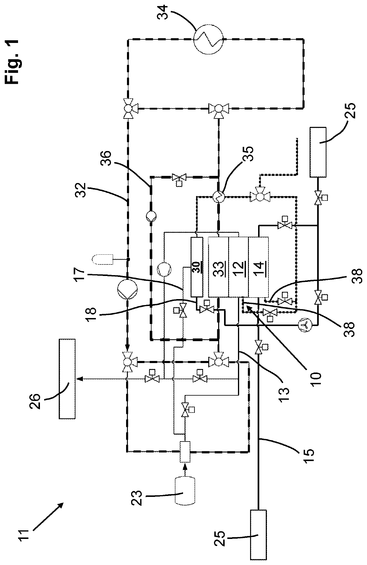
[0027]FIG. 1 shows a schematic illustration of an exemplary energy supply device 11 according to the invention. The at least one anode 12 of the fuel cell 10 is supplied with a fuel via a fuel feed line 13 depicted in FIG. 1 with thin solid lines. In the energy supply device 11 described in the exemplary embodiment, hydrogen, which is stored in a hydrogen tank 23, is fed in as the fuel.

[0028]The at least one cathode 14 of the fuel cell 10 is supplied with ambient air via an air feed line 15, depicted in FIG. 1 by thick solid lines. The ambient air 25 taken from the surroundings or the oxygen contained therein serves as an oxidant for the production of drive energy by the fuel cell 10. The energy supply device 11 further has a converter device 30, to which fuel and ambient air are fed and which serves for producing an inert gas and thermal energy.

[0029]Fuel—hydrogen in the exemplary embodiment, given by way of example—is fed to the converter device 30 of the energy supply device 11 v...


PUM


Abstract

The invention relates to an energy supply device with at least one fuel cell and to a method for operating at least one energy supply device with at least one fuel cell, which has at least one anode that can be supplied with a fuel and at least one cathode that can be supplied with ambient air for generating electrical energy. The proposed energy supply device has a converter device.

Description

BACKGROUND OF THE INVENTION[0001]The invention relates to a method for operating an energy supply device and to an energy supply device with at least one fuel cell, which has at least one anode that can be supplied with a fuel and at least one cathode that can be supplied with ambient air for generating electrical energy.[0002]During operation of a fuel cell, a reductant, such as, for example, hydrogen, is fed to the at least one anode thereof and an oxidant, such as, for example, ambient air, is fed to the at least one cathode thereof. At the anode, the hydrogen is oxidized catalytically to hydrogen ions with the release of electrons. The hydrogen ions reach the cathode region through an electrolyte that is usually present in the form of a membrane and react there with the air oxygen that is fed to the cathode as well as with the electrons that are conducted to the cathode via an external circuit to form water. During the operation of fuel cells, the switched-off phase is very impo...

Claims


Application Information

Patent Timeline
IPC IPC(8): H01M8/0247H01M8/043H01M8/0232
CPCH01M8/0247H01M8/043H01M8/0232H01M2250/20Y02T90/40H01M8/04052H01M8/04007H01M8/04753H01M8/04268H01M8/04731
Inventor LAW, BARNABYHENSS, ANN-KATHRIN
Owner MTU AERO ENGINES GMBH
Why Eureka
Try Eureka