Method and device in nodes used for wireless communication

a wireless communication and node technology, applied in the direction of digital transmission, power management, synchronisation arrangement, etc., can solve the problem of not being able to be directly reused

Pending Publication Date: 2022-09-22
SHANGHAI LANGBO COMM TECH CO LTD
View PDF0 Cites 1 Cited by
  • Summary
  • Abstract
  • Description
  • Claims
  • Application Information

AI Technical Summary

Problems solved by technology

In NTN and similar networks with a great transmission delay and a large transmission delay difference, requirements for a large transmission delay difference and uplink and downlink transmissions with sync may lead to a result that the current (e.g., NR 5G Release 16) design based on traditional Terrestrial Networks cannot be directly reused, particularly, the traditional random access design may not be applicable in NTN, therefore, new designs are required to support networks with large transmission delay and large transmission delay difference to guarantee normal communications.

Method used


Image

  • Method and device in nodes used for wireless communication
  • Method and device in nodes used for wireless communication
  • Method and device in nodes used for wireless communication

Examples


embodiment 1

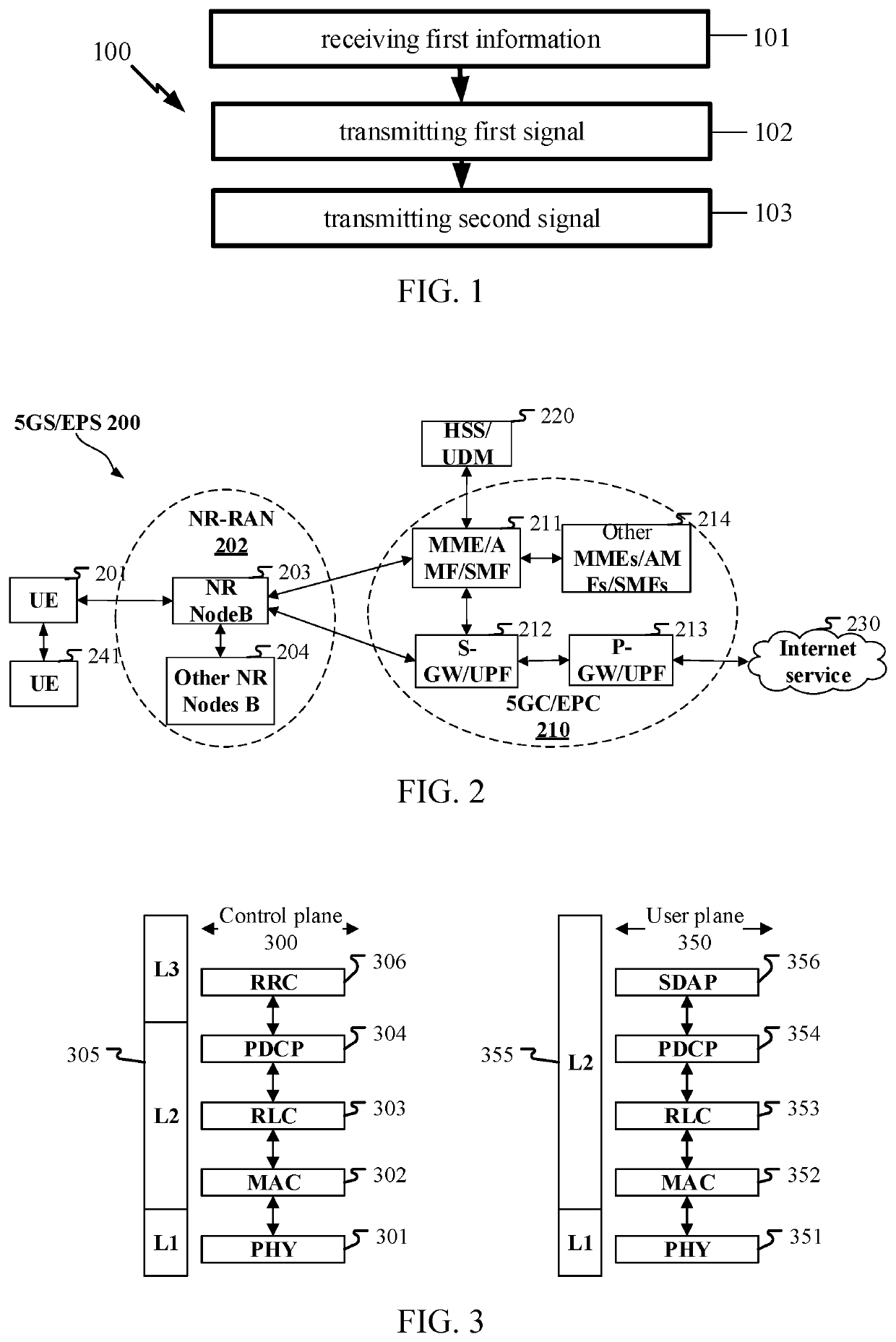
[0094]Embodiment 1 illustrates a flowchart of first information, a first signal and a second signal according to one embodiment of the present disclosure, as shown in FIG. 1. In FIG. 1, each step-size represents a step, it should be particularly noted that the sequence order of each box herein does not imply a chronological order of steps marked respectively by these boxes.

[0095]In Embodiment 1, the first node in the present disclosure receives first information in step 101; transmits a first signal in step 102; and transmits a second signal in step 103; herein, the first information is used to determine X candidate formats, where X is a positive integer greater than 1; the first signal uses a first format; and the second signal uses a second format; the first format is a candidate format among the X candidate formats, and the second format is a candidate format among the X candidate formats, the first format is different from the second format; a first timing offset value is used t...

embodiment 2

[0300]Embodiment 2 illustrates a schematic diagram of a network architecture according to the present disclosure, as shown in FIG. 2. FIG. 2 is a diagram illustrating a network architecture 200 of 5G NR, Long-Term Evolution (LTE) and Long-Term Evolution Advanced (LTE-A) systems. The 5G NR or LTE network architecture 200 may be called a 5G System / Evolved Packet System (5GS / EPS) 200 or other suitable terminology. The 5GS / EPS 200 may comprise one or more UEs 201, an NG-RAN 202, a 5G-Core Network / Evolved Packet Core (5GC / EPC) 210, a Home Subscriber Server / Unified Data Management(HSS / UDM) 220 and an Internet Service 230. The 5GS / EPS 200 may be interconnected with other access networks. For simple description, the entities / interfaces are not shown. As shown in FIG. 2, the 5GS / EPS 200 provides packet switching services. Those skilled in the art will find it easy to understand that various concepts presented throughout the present disclosure can be extended to networks providing circuit swi...

embodiment 3

[0309]Embodiment 3 illustrates a schematic diagram of a radio protocol architecture of a user plane and a control plane according to the present disclosure, as shown in FIG. 3. FIG. 3 is a schematic diagram illustrating an embodiment of a radio protocol architecture of a user plane 350 and a control plane 300. In FIG. 3, the radio protocol architecture for a control plane 300 between a first node (UE, gNB or, terminal device in NTN) and a second node (gNB, UE, or satellite in NTN or aircraft platform), is represented by three layers, i.e., layer 1, layer 2 and layer 3. The layer 1 (L1) is the lowest layer which performs signal processing functions of various PHY layers. The L1 is called PHY 301 in the present disclosure. The layer 2 (L2) 305 is above the PHY 301, and is in charge of the link between a first node and a second node via the PHY 301. The L2 305 comprises a Medium Access Control (MAC) sublayer 302, a Radio Link Control (RLC) sublayer 303 and a Packet Data Convergence Pro...


PUM


Abstract

Method and device in nodes used for wireless communications. A node receives first information, the first information being used to determine X candidate formats; transmits a first signal, the first signal using a first format; and transmits a second signal, the second signal using a second format; the first format is one of the X candidate formats, and the second format is also one of the X candidate formats; a first timing offset value is used to determine a transmission timing for the first signal, while a second timing offset value is used to determine a transmission timing for the second signal, where the first timing offset value is unequal to the second timing offset value; the first format relates to the first timing offset value while the second format relates to the second timing offset value. The present disclosure improves the random access performance.

Description

CROSS REFERENCE TO RELATED APPLICATIONS[0001]This application is the continuation of International patent application PCT / CN2020 / 129030, filed on Nov. 16, 2020, which claims the priority benefit of Chinese Patent Application No. 201911284369.9, filed on Dec. 13, 2019, the full disclosure of which is incorporated herein by reference.BACKGROUNDTechnical Field[0002]The present disclosure relates to transmission methods and devices in wireless communication systems, and in particular to a transmission scheme and a device for random access in wireless communications.Related Art[0003]Application scenarios of future wireless communication systems are becoming increasingly diversified, and different application scenarios have different performance demands on systems. In order to meet different performance requirements of various application scenarios, the 3rd Generation Partner Project (3GPP) Radio Access Network (RAN) #72 plenary decided to conduct the study of New Radio (NR), or what is c...

Claims


Application Information

Patent Timeline
Patent Type & Authority Applications(United States)
IPC IPC(8): H04W74/08H04W72/04H04W52/36
CPCH04W74/0841H04W74/0866H04W72/0446H04W52/362H04W74/0833H04W52/14H04W52/36H04W56/0045H04L27/2602H04L27/2646H04L27/2613H04W52/146
Inventor LIU, ZHENGZHANG, XIAOBO
Owner SHANGHAI LANGBO COMM TECH CO LTD
Why Eureka
Try Eureka