Protective sheet sticking apparatus

a technology of sticking apparatus and protective sheet, which is applied in the direction of chemistry apparatus and processes, synthetic resin layered products, other domestic articles, etc., can solve the problems of increasing the obstacle of protecting sheet, so as to increase the size of the apparatus and the cost of increasing

Active Publication Date: 2022-09-29
DISCO CORP
View PDF2 Cites 0 Cited by
  • Summary
  • Abstract
  • Description
  • Claims
  • Application Information

AI Technical Summary

Benefits of technology

[0003]In such a protective sheet sticking apparatus, the cutting blade moves along the outer circumferential edge of the wafer and cuts the protective sheet along the circular wafer. Thereafter, the wafer is thinned by a grinding apparatus or a polishing apparatus or is processed by a laser beam. Normally, the wafer has an orientation flat or notch that indicates the direction of the crystal orientation at the outer circumference. Even when the protective sheet is cut along the circular shape, if the direction of the cutting edge of the cutting blade is not caused to be along the orientation flat in particular, the cut protective sheet widely protrudes from the wafer. Therefore, the protective sheet becomes an obstacle in the next step and interferes with grinding or the like. Thus, separately from the method of cutting the protective sheet for the circular part, a method in which a table or the cutting blade is moved along the shape of the orientation flat to cut the protective sheet is executed for the part of the orientation flat. In this case, there is a problem that an actuator for control of the table or the cutting blade is required, and therefore the size of the apparatus becomes larger, and the cost increases.

Problems solved by technology

Therefore, the protective sheet becomes an obstacle in the next step and interferes with grinding or the like.
In this case, there is a problem that an actuator for control of the table or the cutting blade is required, and therefore the size of the apparatus becomes larger, and the cost increases.

Method used


Image

  • Protective sheet sticking apparatus
  • Protective sheet sticking apparatus
  • Protective sheet sticking apparatus

Examples


Embodiment Construction

[0018]An embodiment of the present invention will be described in detail below with reference to the drawings. The present invention is not limited by contents described in the following embodiment. Furthermore, what can be easily envisaged by those skilled in the art and what are substantially the same are included in constituent elements described below. Moreover, configurations described below can be combined as appropriate. In addition, various kinds of omission, replacement, or change of a configuration can be carried out without departing from the gist of the present invention.

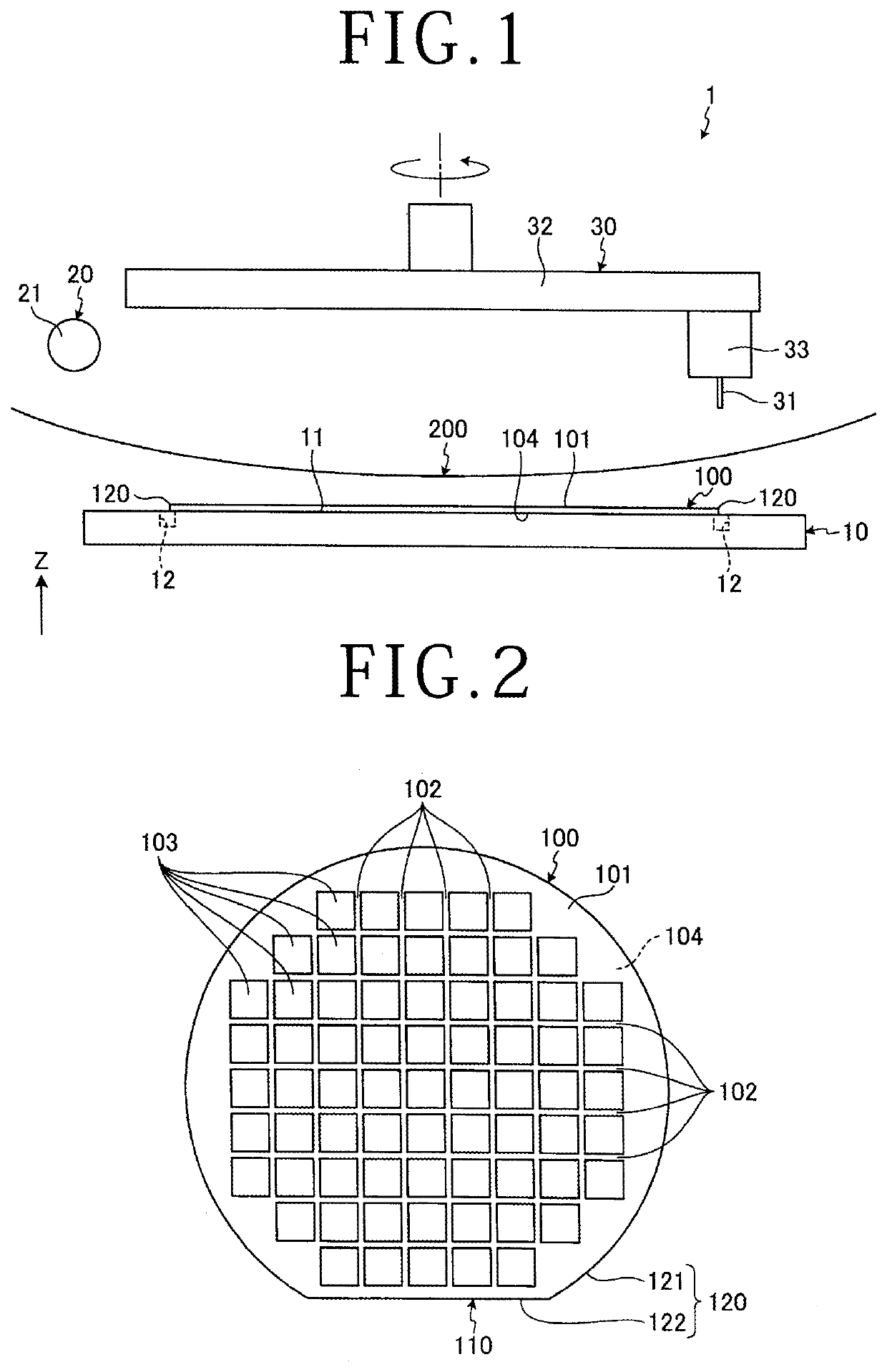
[0019]A protective sheet sticking apparatus 1 according to the embodiment of the present invention will be described on the basis of the drawings. FIG. 1 is a sectional view illustrating a configuration example of the protective sheet sticking apparatus 1 according to the embodiment. FIG. 2 is a plan view illustrating a wafer 100 that is a sheet sticking target of the protective sheet sticking apparatus ...


PUM

PropertyMeasurementUnit
cutting edge inclination angleaaaaaaaaaa
circular shapeaaaaaaaaaa

Abstract

A protective sheet sticking apparatus includes a cutting unit that cuts a protective sheet stuck to a wafer along an outer circumference of the wafer while bringing a cutting part of a cutting blade into contact with the outer circumference of the wafer. The cutting unit has a cutting blade support part that supports the cutting blade rotatably in such a manner that the direction of a cutting edge of the cutting part is adjustable from the outside in the radial direction of the wafer to the inside. The cutting blade support part includes a first biasing spring that makes biasing to cause the cutting part to be oriented toward the inside and a second biasing spring that makes biasing to cause the cutting part to be oriented toward the outside in order to prevent the cutting part from being oriented toward the inside by a predetermined angle or larger.

Description

BACKGROUND OF THE INVENTIONField of the Invention[0001]The present invention relates to a protective sheet sticking apparatus.Description of the Related Art[0002]Conventionally, in a semiconductor manufacturing process, a protective sheet sticking apparatus that sticks a protective sheet such as a protective tape to a surface of a wafer as an adherend in which plural semiconductor devices are formed and cuts the stuck protective sheet by a cutting blade along the outer edge of the wafer is used (for example, refer to Japanese Patent Laid-open No. 2006-005131).SUMMARY OF THE INVENTION[0003]In such a protective sheet sticking apparatus, the cutting blade moves along the outer circumferential edge of the wafer and cuts the protective sheet along the circular wafer. Thereafter, the wafer is thinned by a grinding apparatus or a polishing apparatus or is processed by a laser beam. Normally, the wafer has an orientation flat or notch that indicates the direction of the crystal orientation ...

Claims


Application Information

Patent Timeline
Patent Type & Authority Applications(United States)
IPC IPC(8): H01L21/67B32B37/12B32B38/00B32B27/06B32B7/12
CPCH01L21/67132B32B37/12B32B38/105B32B27/06B32B7/12B32B2457/14B29C63/02B29C63/0004B29C69/001B26F3/08B26D7/2614B26D7/2628H01L21/67092H01L21/6836H01L2221/6834
Inventor KAKINUMA, YOSHINORI
Owner DISCO CORP
Why Eureka
Try Eureka