
Inkjet printing apparatus and method of controlling the apparatus

a technology of printing apparatus and control apparatus, which is applied in the direction of control system, printing, electric motor control, etc., can solve the problems of insufficient filling, inability to smoothly perform ink supply, and insufficient supply, so as to improve the performance of pressure generating unit, increase the size of the apparatus, and improve the effect of pressur

Inactive Publication Date: 2009-11-26
CANON KK
View PDF6 Cites 1 Cited by
  • Summary
  • Abstract
  • Description
  • Claims
  • Application Information

AI Technical Summary

Benefits of technology

[0014]To overcome this problem, in the conventional technology, a mechanical sensor is provided for detecting a phase of the pump, and operations of the pump are controlled according to the detected pump phase. For instance, in the tube pump, a flag is provided in a rotary section of the pump for detecting a phase of a roller, and also a unit for detecting a roller phase with a sensor such as a photo interrupter is provided therein. Therefore, in the inkjet printing apparatus based on the conventional technology, the cost increases and size of the apparatus becomes larger in association of provision of a specific pump phase detecting unit.
[0024]The present invention employs a control system in which an electric power supplied to a motor is changed according to load fluctuations and a phase of a pressure generating unit (pump) is determined based on a result of detection of the supplied power. With the configuration described above, it is possible to manage a pressure generated by the pressure generating unit and a discharge rate of ink with a low-cost configuration not requiring any specific unit for detection.

Problems solved by technology

However, there are several problems as described below in the conventional type of inkjet printing apparatuses having a pressure generating unit.
In this case, however, when the negative pressure is too high, an ink supply rate in an ink supply path from an ink tank up to a nozzle is inadequate, and sometimes ink supply can not be performed smoothly, which is disadvantageous.
Because of the phenomenon, there occur the troubles, for instance, that ink is insufficiently filled, that the cleaning capability becomes unstable, or that the ink is excessively consumed and the running cost disadvantageously increases.

Method used


Image

  • Inkjet printing apparatus and method of controlling the apparatus
  • Inkjet printing apparatus and method of controlling the apparatus
  • Inkjet printing apparatus and method of controlling the apparatus

Examples


first embodiment

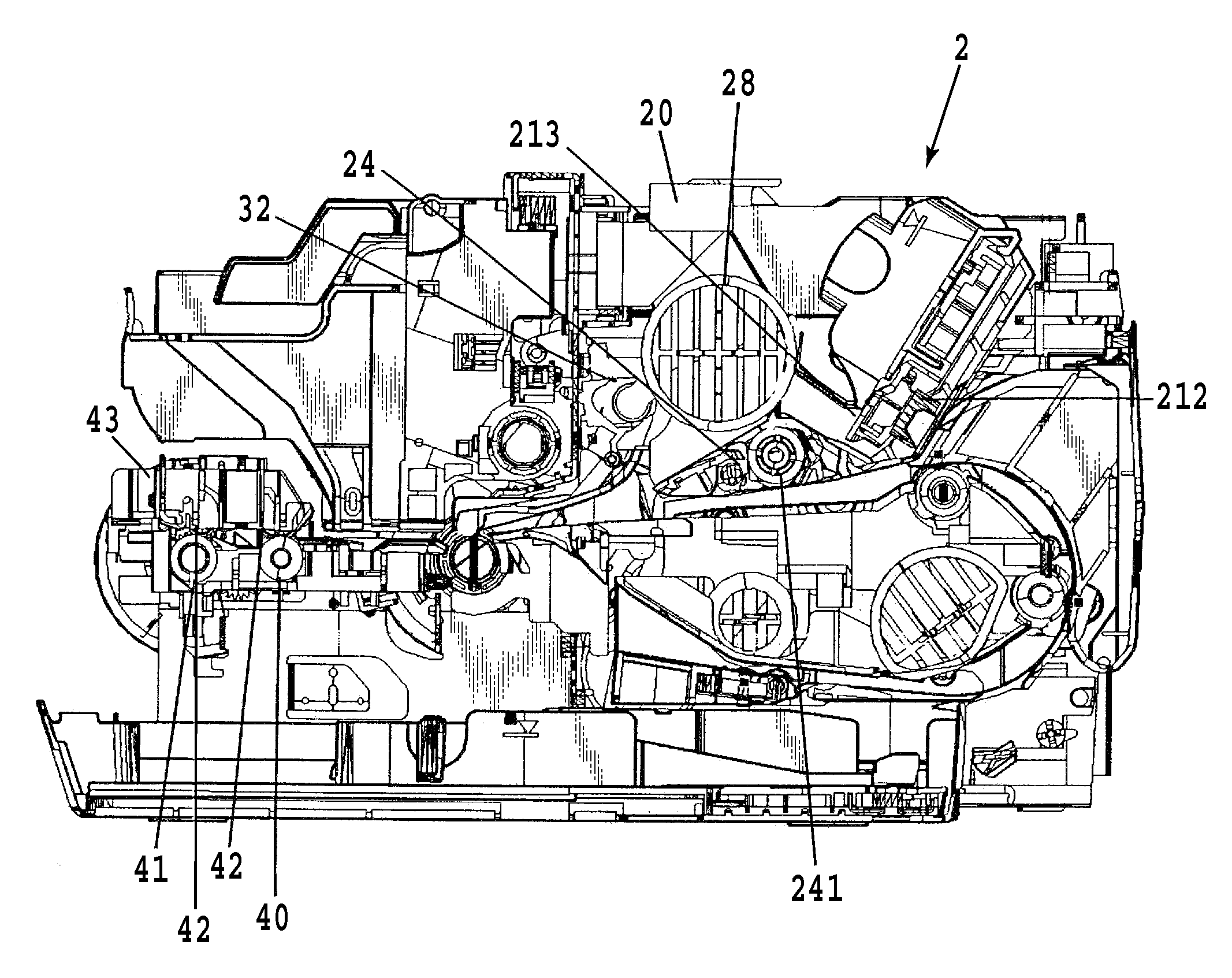
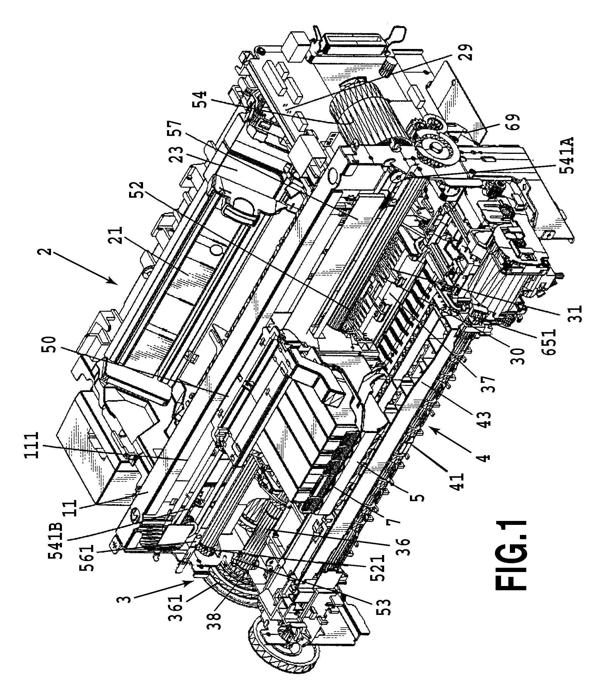
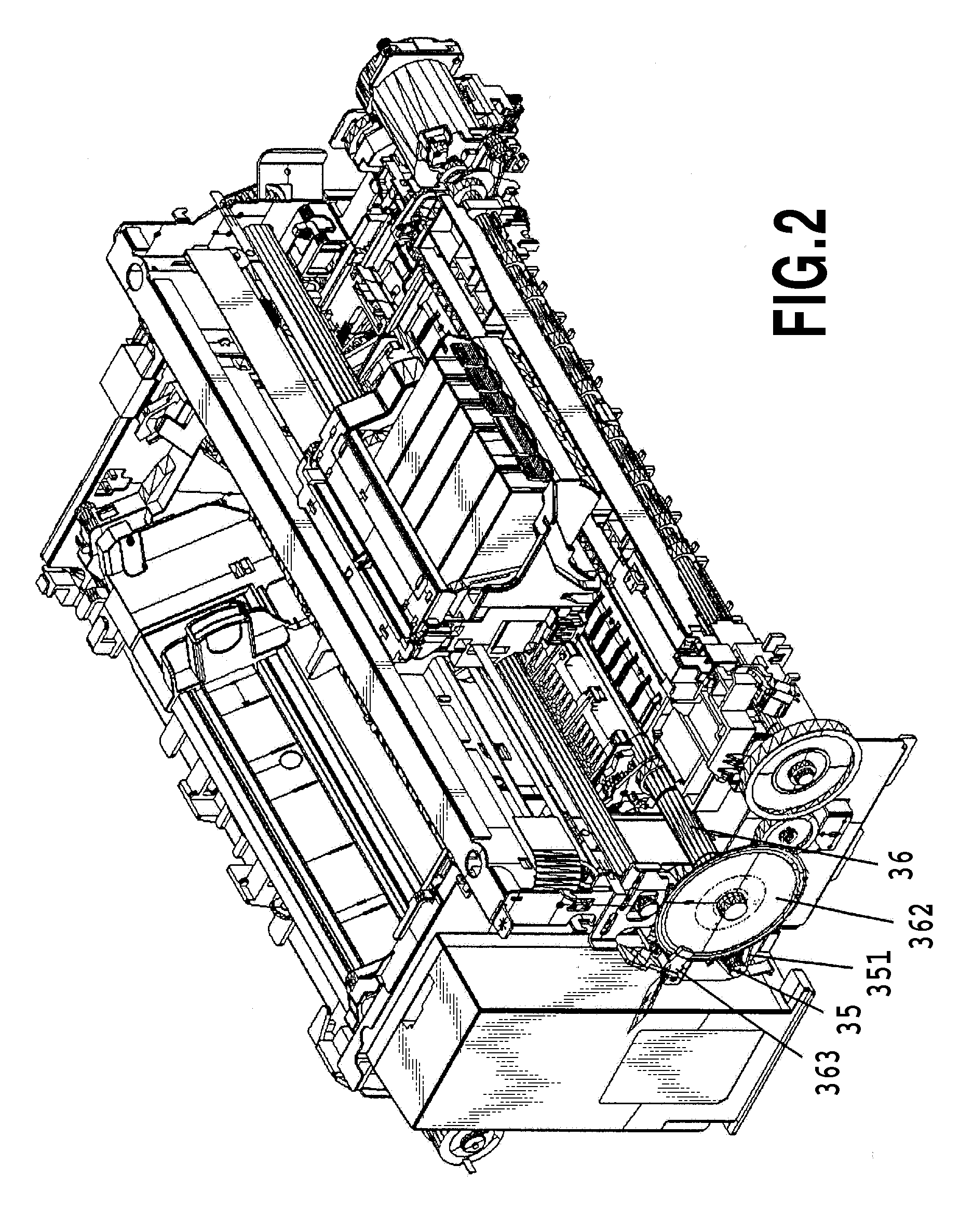
[0045]An inkjet printing apparatus (also referred to simply as “printing apparatus” hereinafter) according to a first embodiment of the present invention with reference to FIG. 1 to FIG. 12. FIG. 1 and FIG. 2 are views illustrating the printing apparatus according to the first embodiment viewed in different directions respectively, and FIG. 3 is a lateral cross-sectional view of the printing apparatus. FIG. 4 is a view illustrating a printing head applied in the embodiment viewed from the ejection face side. FIG. 5 and FIG. 6 are perspective views illustrating a cleaning unit in the printing apparatus according to the first embodiment in different directions respectively; FIG. 7 is a view schematically showing an ink suction mechanism in the cleaning unit; FIG. 8 and FIG. 9 are cross-sectional views each showing a pump in the cleaning unit; and FIG. 10 is a perspective view illustrating the pump. FIG. 11 is a block diagram illustrating an example of a configuration of a control syst...

second embodiment

[0092]A second embodiment of the present invention is described below with reference to FIG. 14 and FIG. 15. FIG. 14 is a cross-sectional view schematically showing a configuration in which a tube is pressed by a dual sucking pump constituting a plurality of pressure generating unit, namely by two pump elements (rollers). FIG. 15 is a graph showing a current PWM value for a source of a driving force.

[0093]As described above, to optimize the processes performed in a printing apparatus for resolving clogging or for sucking ink for filling, it is required to manage a pressure generated by a pressure generating unit and a discharge rate extremely precisely. To achieve the object, in an inkjet printing apparatus having a plurality of pump elements, it is necessary to detect phases of the plurality of pump elements at positions for generation of a negative pressure, and also to determine each of the phases. When power sources, phase detection sensors, load fluctuation detecting units and ...

third embodiment

[0110]A third embodiment of the present invention is described below with reference to FIG. 16 and FIG. 17. FIG. 16 is a cross-sectional view schematically showing a dual pump system according to the third embodiment, and FIG. 17 is a graph showing a current PWM value for a source of a driving force in this embodiment.

[0111]A configuration similar to that in the second embodiment is employed in the third embodiment, but the third embodiment is different from the second embodiment in the point that a first roller 821 and a second roller 822 are located out of alignment by about 180 degrees in the rotating direction. Furthermore, a projection 824 for generating load fluctuations is provided at a position where the projection 824 acts only to the first roller 821 in the inner side from a pump base 823. This projection 824 is located at a position displaced by a certain angle in the rotational direction of the first roller 821 from a tube-overlapped position by arranging the tube over a...


PUM


Abstract

In order to stabilize a performance of a pump employed for processing in an inkjet printing apparatus such as sucking ink from a printing head with a low cost configuration and without the need of using any specific detecting unit, the following configuration is employed. Namely, a tube pump having a member with a curved surface aligned with a flexible tube for supporting the tube and a roller which moves while pressing (squeezing) the flexible tube is driven with a DC motor. To keep revolutions always constant, a current PWM control is employed for changing a power applied to the motor according to load fluctuations, and a phase of the roller is determined based on the current PWM value to manage a pressure generated by the pump and a discharge rate.

Description

TECHNICAL FIELD[0001]The present invention relates to an inkjet printing apparatus and a method of controlling the apparatus, and more specifically to an inkjet printing apparatus having a unit for generating a pressure for processing performed within the apparatus by making use of the pressure and a method of controlling the apparatus.BACKGROUND ART[0002]An inkjet printing apparatus is used for printing an image on a printing medium by ejecting ink from a printing unit (a printing head), and has the advantage that downsizing of the printing unit is easy and an extremely fine image can be printed at a high speed. Furthermore, because printing can be performed even on plain paper without needing any specific processing, the inkjet printing apparatus also has the advantage that the running cost is low. In addition, there are the advantages that the inkjet printing system is a non-impact printing system and therefore noises are small, and that the printing system can easily be applied ...

Claims


Application Information

Patent Timeline
Patent Type & Authority Applications(United States)
IPC IPC(8): B41J29/38
CPCB41J2/17596Y10S388/93
Inventor SHIGENO, KENJIISHIKAWA, TETSUYAYANAGI, HARUYUKIONUMA, KENTARO
Owner CANON KK
Learn More