
Tool kit for detecting leakages in tubes

Inactive Publication Date: 2022-10-13
ALMEGHRABI HAMZAH G
View PDF2 Cites 0 Cited by
  • Summary
  • Abstract
  • Description
  • Claims
  • Application Information

AI Technical Summary

Benefits of technology

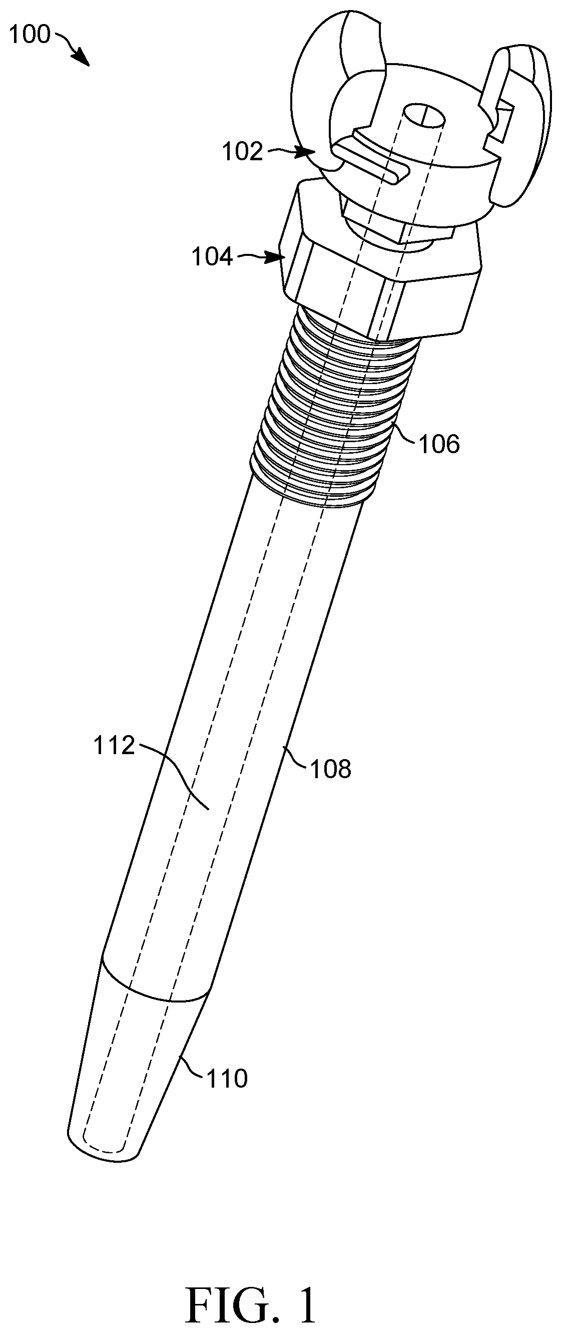
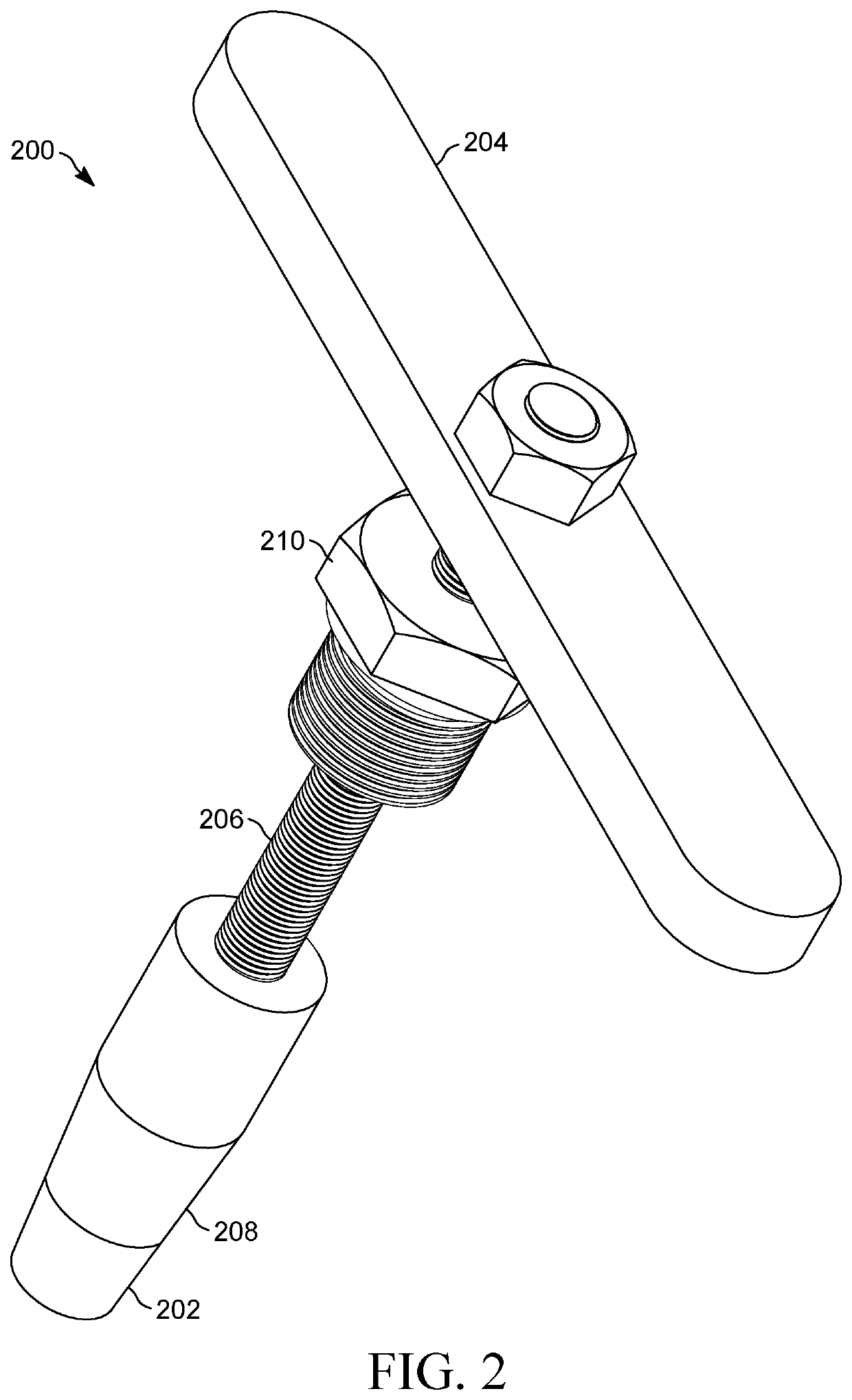
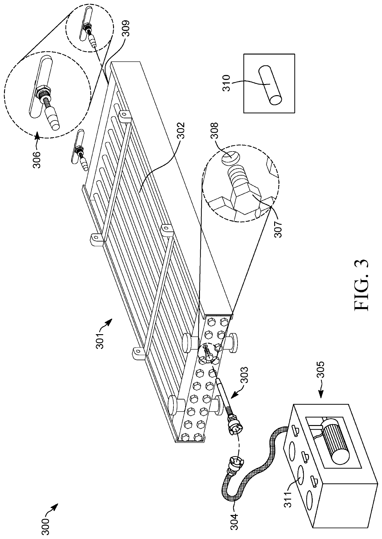
The present invention is a tool kit that can be used to detect leaks in tubes used in heat exchanges systems. It is easy to assemble and can be controlled manually. It has an inlet and an outlet with a tapered structure that makes it easy to insert within tubes. The tool kit is lightweight and portable. It attaches to the extreme ends of the tubes and identifies any pressure drops for a set period of time. Overall, the invention provides an effective and reliable solution for detecting leaks in tubes.

Problems solved by technology

But the major drawback in hydrostatic testing and the pneumatic test for detecting leakage in the tubes is that these tests must always be performed under controlled conditions.
As these tests are performed under controlled conditions, there are high chances of breaking of the tubes if the water pressure or the air pressure supplied to the tubes of the heat exchanger system is extremely high.
But the main drawback of this technology is that a breakage might occur in the heat transfer tube if the pressure of the gas may go extremely high into the heat transfer tube, due to which leakage can occur easily in the heat transfer tube.
But the major drawback in this technology is that due to movement of rotary member, the wedge is tensioned for maintaining continuous outward sealing pressure against the inside of the tube over a wide range of conditions which might tend to loosen the plug assembly and cause leakage of pipe due to continuous sealing pressure.
The primary challenge with the above aforementioned technologies to detect leakage in the tubes of the industrial machines is the prevention of tubes from breaking on the application of high pressure of fluid or any other medium such as air, gas passing through the tubes.
Also one of the secondary challenges in the prior tube leakage detection systems is that whenever a fluid flows through the tubes of the heat exchanger in a turbulent manner (as in the turbulent flow of liquid), the eddy currents are produced due to high velocity of fluid particles and heavy accumulated scales around the surface of the tubes.
This leads to friction caused between fluid layers and any puncture in the tubes of the heat exchanger system due to the friction is indicated by leakage of magnetic flux inside the tubes, resulting in a change of magnetic field in the heat exchanger.
The puncture in the tubes can lead to damage to the testing kit which is used to test the tubes for any magnetic flux leakage.
Thus, the inability of these present systems to determine leakage of magnetic flux inside the tubes of the industrial machines in order to overcome magnetic flux leakage test limitations and uncertainty due to heavy accumulated scales is one of the secondary challenges which needs to be addressed.
Further, limitations and disadvantages of conventional and traditional approaches will become apparent to the one skilled in the art through comparison of the described system with some aspects of the present disclosure, as set forth in the remainder of the present application and with reference to the drawings.

Method used


Image

  • Tool kit for detecting leakages in tubes
  • Tool kit for detecting leakages in tubes
  • Tool kit for detecting leakages in tubes

Examples


Embodiment Construction

[0041]Embodiments of the present invention disclosure will be described more fully hereinafter with reference to the accompanying drawings in which like numerals represent like elements throughout the figures, and in which example embodiments are shown.

[0042]The detailed description and the accompanying drawings illustrate the specific exemplary embodiments by which the disclosure may be practiced. These embodiments are described in detail to enable those skilled in the art to practice the invention illustrated in the disclosure. It is to be understood that other embodiments may be utilized, and other changes may be made, without departing from the spirit or scope of the present disclosure. The following detailed description is therefore not to be taken in a limiting sense, and the scope of the present invention disclosure is defined by the appended claims. Embodiments of the claims may, however, be embodied in many different forms and should not be construed as limited to the embod...


PUM


Abstract

A tool kit for testing and detecting a leakage in a tube having a cylindrical body is disclosed herein. The tool kit of the present invention comprises an inlet member and an outlet member which are going to attached with the extreme ends of the tube through a threaded mechanism. The one end of both inlet member and outlet member has a tapered structure that allows the easy insertion of both members in the openings of the tube. The tool kit further includes a fluid pump that pumps the fluid in the tube, wherein the fluid is inserted through the inlet member of the tool kit. A pressure monitoring unit is also provided with the fluid pump that measures the pressure inside the tube in real time. Furthermore, the outlet member includes a handle whose function is to control the pressure inside the tube during the testing process.

Description

TECHNICAL FIELD[0001]The subject matter of the present invention relates generally to the field of leakage testing kits. More particularly, the subject matter of the present invention relates to a tube leakage testing kit and a method for testing the leakage in the tube used in a heat exchanger system.BACKGROUND ART[0002]Many industrial systems and machines are used to transfer heat between two or more fluids as they are used in both cooling and heating processes. One of the most common examples of such industrial machines is a heat exchanger. These industrial systems and machines mainly consist of a series of tubes that contains fluid that must be either heated or cooled. The series of the tubes is called a tube bundle. The tubes are composed of various materials and the most commonly used tubes nowadays are made up of steel material. A hydro-test is usually performed to check for leakage in the tubes irrespective of their material of which they are composed. The most common test p...

Claims


Application Information

Patent Timeline
IPC IPC(8): G01M3/28
CPCG01M3/2815F28F27/00G01M3/2846G01M3/022F28F2200/00
Inventor ALMEGHRABI, HAMZAH G.
Owner ALMEGHRABI HAMZAH G
Learn More