Reusability Determination Method for Gear and Reusability Determination System for Gear

a technology of reusability determination and gear, which is applied in the direction of machine parts testing, structural/machine measurement, instruments, etc., can solve the problems of high cost of gear parts that compose speed reducers or the like, and achieve the determination of reusability by non-destructive inspection, high reliability, and the effect of reusability of a gear

Pending Publication Date: 2022-10-13
NIHON KENKI CO LTD
View PDF0 Cites 0 Cited by
  • Summary
  • Abstract
  • Description
  • Claims
  • Application Information

AI Technical Summary

Benefits of technology

[0014]According to the present invention, reusability of a gear can be determined reasonably from the reference point for reusability determination that is derived from the correlation between the decrease rate of the retained γ phase and the increase rate of the residual stress ratio. Further, according to the present invention, determination of reusability by non-destructive inspection can be implemented. As a result, it becomes possible to perform reusability determination simply and objectively for a gear also including full scrap gear parts for which even visual inspection has not been carried out so far. Consequently, it is possible to construct a quality control technology having high reliability, reduce the scrap rate significantly, and reduce the part cost.

Problems solved by technology

Gear parts that compose a speed reducer or the like are expensive and are frequently used in an environment in which it is difficult to acquire them.

Method used


Image

  • Reusability Determination Method for Gear and Reusability Determination System for Gear
  • Reusability Determination Method for Gear and Reusability Determination System for Gear
  • Reusability Determination Method for Gear and Reusability Determination System for Gear

Examples


first embodiment

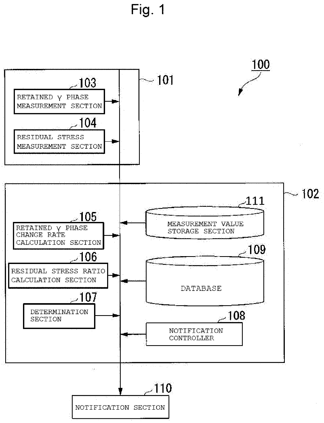
[0030]FIG. 1 is a view schematically depicting a configuration of a reusability determination system 100 for a gear according to a first embodiment of the present invention. The reusability determination system 100 for a gear is a reusability determination system for a gear during or after use, and includes a measuring apparatus 101 and a determination apparatus 102 as principal components thereof. The measuring apparatus 101 includes a retained γ phase measurement section 103 and a residual stress measurement section 104 as principal components thereof. The determination apparatus 102 includes a retained γ phase change rate calculation section 105, a residual stress ratio calculation section 106, and a determination section 107 as principal components thereof.

[0031]The retained γ phase measurement section 103 is a measuring device that measures the content of the retained γ (austenite) phase (face-centered cubic lattice) in a gear. The retained γ phase is a carburized tempered mart...

example

[0055]In the following, the advantageous effects of the present invention are made clearer from the examples. It is to be noted that the present invention is not limited to the following examples and can be carried out in suitably modified forms without departing from the subject matter thereof.

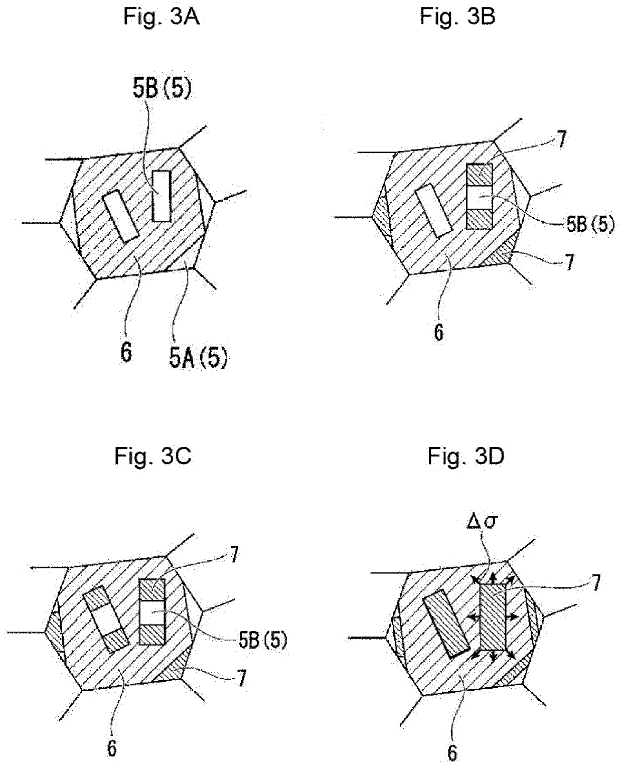
[0056]Electropolishing was performed for a gear before and after operation to expose the retained γ phases on a tooth face of the gear, and the distribution state of the retained y phases was imaged using a scanning electron microscope (SEM). FIGS. 6A to 6C are SEM images (structure photographs) of a gear before operation, a gear 1 recovered after operation and a gear 2 recovered after operation. The field of view has a depth of approximately 20 μm from the gear surface layer and a width of approximately 25 μm along the gear surface layer. From the SEM images, the presence of martensite phases 6 lined up like a plate can be confirmed. Further, in the martensite phases 6, also carbide 7 can be...


PUM


Abstract

Provided is a reusability determination method for a gear that makes it possible to determine reusability of a gear during or after use to increase the reuse ratio. The reusability determination method for a gear of the present invention includes a step of measuring a content of retained γ phases in the gear, a step of calculating a change rate of the content of the retained γ phases, a step of measuring residual stress applied to the gear, a residual stress ratio calculation step of calculating a residual stress ratio to residual stress in an initial state of the gear, and a reusability determination step of determining whether or not the gear is reusable on the basis of results of the calculation in the retained γ phase change rate calculation step and the residual stress ratio calculation step. In the reusability determination step, it is determined that the gear is reusable where the state of the gear corresponds to a first phase P1 or a second phase P2 from among the first phase P1, the second phase P2, and a third phase P3, and it is determined that the gear is not reusable where the state of the gear corresponds to the third phase P3.

Description

TECHNICAL FIELD[0001]The present invention relates to a reusability determination method for a gear and a reusability determination system for a gear.BACKGROUND ART[0002]Gear parts that compose a speed reducer or the like are expensive and are frequently used in an environment in which it is difficult to acquire them. Therefore, it is required to take out gear parts from a speed reducer after it has operated for a fixed period of time and make predetermined evaluation on them and then reuse those gear parts that are found as sound. In a process at present, only gear parts on which the load is comparatively low are subjected to visual confirmation by a worker about whether or not exfoliation appears on the tooth surface thereof, and determination of whether or not they are reusable is made. Thus, approximately one half of the gear parts do not suffer from exfoliation of tooth surface and are reused. Gear parts on which the load is high are discarded uniformly at the stage where a pre...

Claims


Application Information

Patent Timeline
Patent Type & Authority Applications(United States)
IPC IPC(8): G01M13/021
CPCG01M13/021Y02P10/20
Inventor KANAZAWA, TOMOHISAYOSHIMOTO, MITSUHIROHATA, NORIHITOHAYAKAWA, MASAOMEGURO, SUSUMUHIROTO, TAKANOBUMATSUSHITA, YOSHITAKA
Owner NIHON KENKI CO LTD
Why Eureka
Try Eureka