Electrified tractor and computer-readable medium

a technology of electronic tractor and computer, which is applied in the direction of tractor, battery/fuel cell control arrangement, non-skid device, etc., can solve the problems of tractor not being able to escape from the mud, the output torque of electric motor might become insufficient,

Pending Publication Date: 2022-11-03
TOYOTA JIDOSHA KK
View PDF6 Cites 0 Cited by
  • Summary
  • Abstract
  • Description
  • Claims
  • Application Information

AI Technical Summary

Problems solved by technology

Accordingly, when the tractor tries to escape from the mud, the farm field, or the like under the situation where input-output electric power of the battery is restricted as described above, the output torque of the electric motor might become insufficient, and the tractor might not be able to escape from the mud, the farm field, or the like.

Method used


Image

  • Electrified tractor and computer-readable medium
  • Electrified tractor and computer-readable medium
  • Electrified tractor and computer-readable medium

Examples


first embodiment

[0023]Overall Configuration of Electrified Tractor

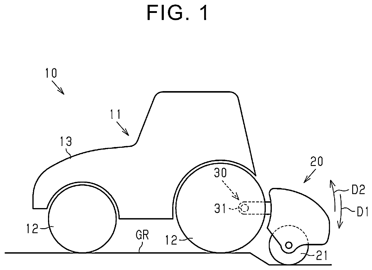
[0024]As illustrated in FIG. 1, an electrified tractor 10 includes a vehicle 11, a work machine 20, and a support mechanism 30. The vehicle 11 includes a plurality of wheels 12 and a vehicle body 13. The wheels 12 are connected to the vehicle body 13. The vehicle body 13 can be connected to the work machine 20 via the support mechanism 30.

[0025]The work machine 20 is placed behind the vehicle 11. The work machine 20 includes a plurality of blades 21 for cultivation. The work machine 20 can cultivate a farm field by rotating the blades 21 in a state where the blades 21 make contact with a ground GR of the farm field. Note that, in FIG. 1, the blades 21 are simplified and illustrated in a cylindrical shape.

[0026]The support mechanism 30 connects the vehicle body 13 to the work machine 20. The support mechanism 30 includes a support shaft 31. Although not illustrated herein, the support mechanism 30 includes a plurality of rods, a hydra...

second embodiment

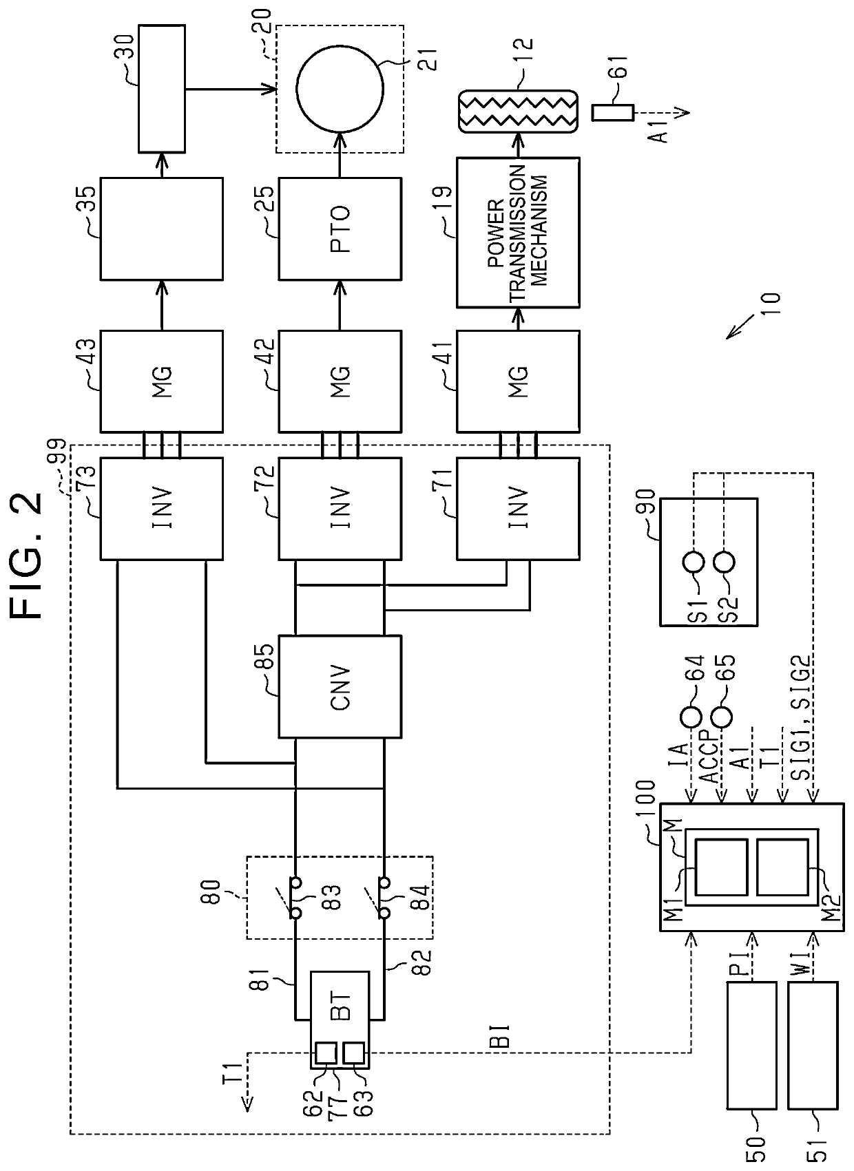
[0097]The following describes a second embodiment of the electrified tractor and the control program for the electrified tractor. In the second embodiment, the schematic configuration of the electrified tractor 10, the power transmission path in the electrified tractor 10, the electrical configuration of the electrified tractor 10, and the schematic configuration of the control device 100 are the same as those in the first embodiment.

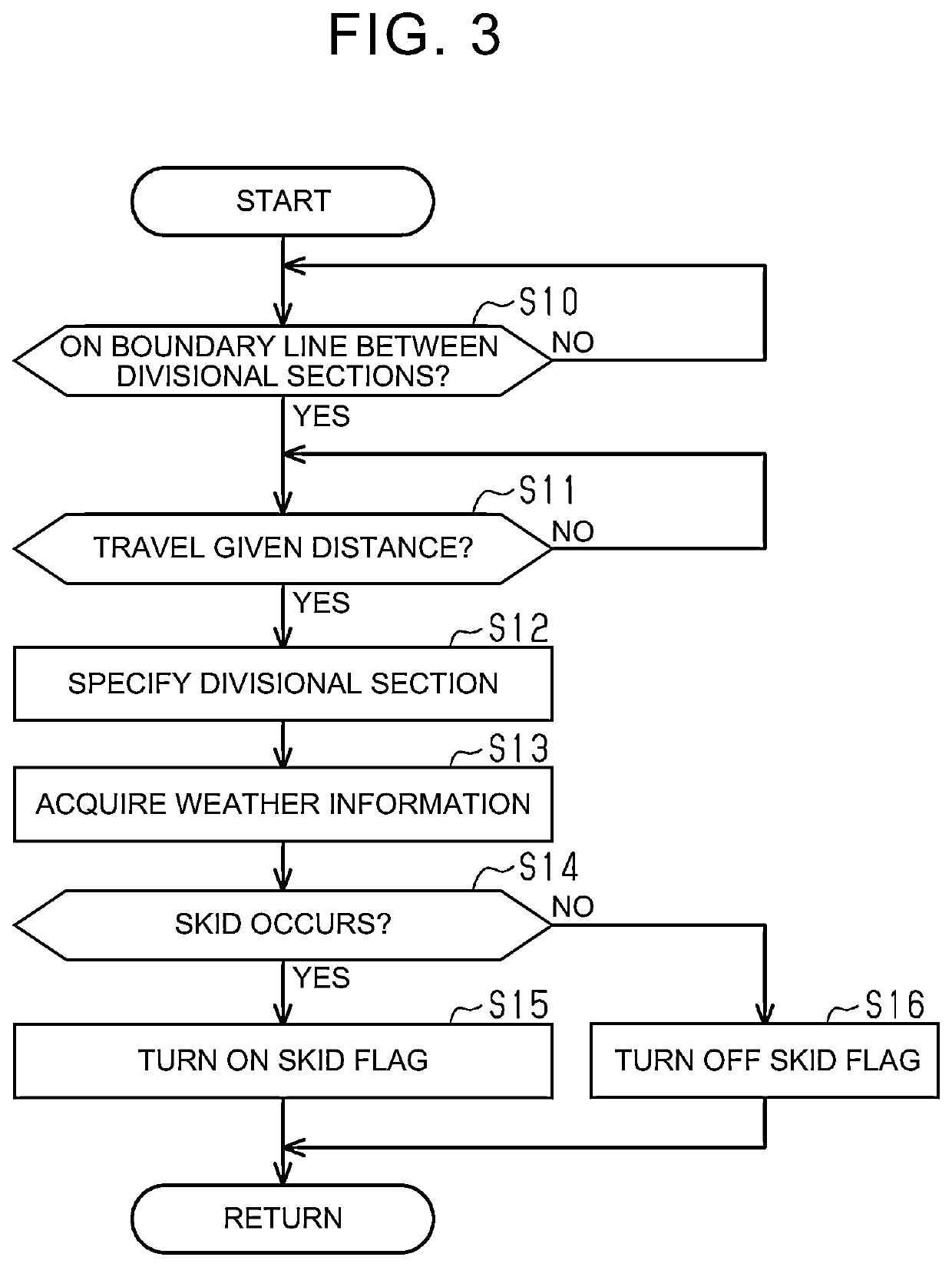
[0098]Farm Field Escape Control

[0099]The control device 100 executes the farm field escape control. The farm field escape control is started on condition that the electrified tractor 10 is placed inside the farm field. That is, the control device 100 acquires present position information PI on the electrified tractor 10 from the GPS device 50. Further, the control device 100 starts the farm field escape control on condition that a present position of the electrified tractor 10 is placed inside a region shown on the farm field map M based on the position...


PUM


Abstract

An electrified tractor includes a vehicle body, an electric motor, a battery, an inverter configured to control input-output electric power of the battery, a wheel for traveling, and a control device. On condition that the electrified tractor travels inside a restriction area determined in advance as one condition, the control device controls the inverter such that the input-output electric power of the battery falls within a specific electric power range determined in advance. The control device determines whether or not there is a possibility that the electrified tractor moves from the restriction area to outside the restriction area. In a case where an affirmative determination is made in a determination process during a restriction process, the control device expands the specific electric power range as compared with a case where a negative determination is made in the determination process.

Description

CROSS-REFERENCE TO RELATED APPLICATION[0001]This application claims priority to Japanese Patent Application No. 2021-077739 filed on Apr. 30, 2021, incorporated herein by reference in its entirety.BACKGROUND1. Technical Field[0002]The present disclosure relates to an electrified tractor and a computer-readable medium.2. Description of Related Art[0003]A tractor described in Japanese Unexamined Patent Application Publication No. 2014-143965 (JP 2014-143965 A) includes a battery, an electric motor, wheels, and a work machine. The battery supplies electric power to the electric motor. The electric motor is driven upon receipt of electric power from the battery. Driving force from the electric motor is transmitted to the wheels and the work machine. That is, the tractor described in JP 2014-143965 A travels with the electric motor being used as a drive source.SUMMARY[0004]As a technology for the tractor as described in JP 2014-143965 A, there has been known a technology to restrict inpu...

Claims


Application Information

Patent Timeline
Patent Type & Authority Applications(United States)
IPC IPC(8): B60L15/20B60K17/28B60C27/02B62D49/06
CPCB60L15/20B60K17/28B60C27/02B62D49/0692B60L2200/40B60L2210/40B60L50/60B60L58/12B60L58/10B60L3/10B60L2240/54Y02T10/70B60L58/13B60L2240/545B60L58/25Y02T10/72B60K1/04B60K1/00B60K1/02B60Y2200/221
Inventor SUGO, YUKI
Owner TOYOTA JIDOSHA KK
Why Eureka
Try Eureka