
Sealed and thermally insulating tank having inter-panel insulating inserts

a technology of inter-panel insulating inserts and seals, which is applied in the direction of vessel construction details, transportation and packaging, passenger handling devices, etc., can solve the problems of void separation of flat insulating seals, inability to ensure the seals are sealed, and inability to reliably

Pending Publication Date: 2022-11-03
GAZTRANSPORT & TECHNIGAZ
View PDF0 Cites 0 Cited by
  • Summary
  • Abstract
  • Description
  • Claims
  • Application Information

AI Technical Summary

Benefits of technology

The invention aims to provide a tank wall that produces a sealed and thermally insulating tank that does not have any voids between the panels. This is achieved by using an insulating insert that fills the space between adjacent panels, and a method that includes cutting the lateral faces of the wrapper to improve gas circulation. The technical effect is to improve the insulation of the tank and prevent any leakage, which can save energy and protect the contents from damage.

Problems solved by technology

Further, these insulating seals are unable to ensure that such insulating seals optimally fill all of the inter-panel space.
Thus, such insulating seals are unable reliably to ensure the continuity of the insulation in the thermally insulating barriers which means that spaces prone to convection phenomena may be present in the thermally insulating barriers.
Thus, the applicant has noticed that these flat insulating seals contract more than the inter-panel space in which they are housed and that this contraction results in a void separating the flat insulating seal from the faces of the panels that delimit the inter-panel space.
Such a void encourages convection phenomena and is detrimental to the insulating characteristics of the thermally insulating barrier.
Further, such separators provide a head loss in the thickness direction of the tank wall that limits convection through the layered glass wool in the tank wall.
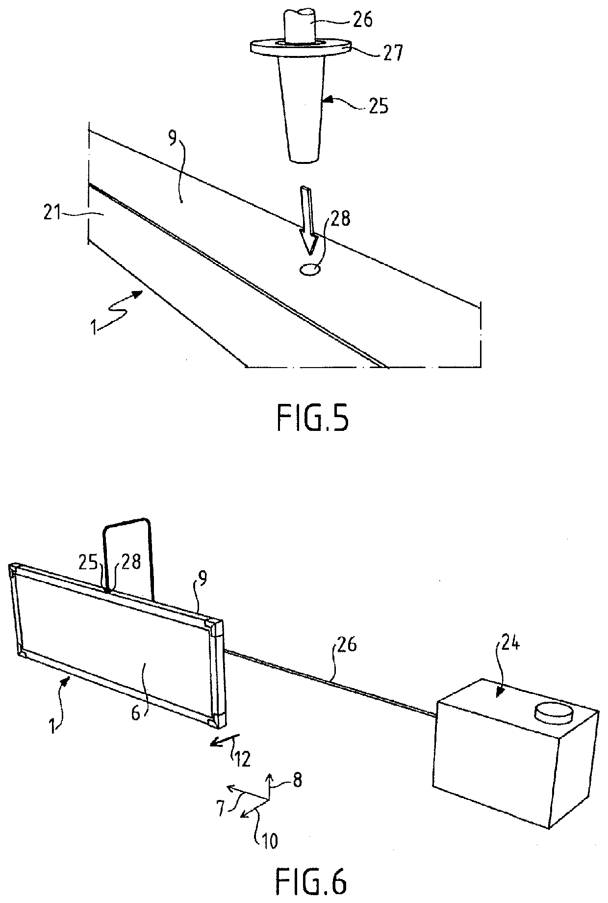
Further, this insertion of the end of the nozzle of the suction system via a lateral face of the wrapper allows the insulating insert to be compressed without the need for too high a pumping flow rate by the suction system, thus limiting the risks of wrapper damage which are associated with too much suction detrimental to the compression of the insulating insert.

Method used

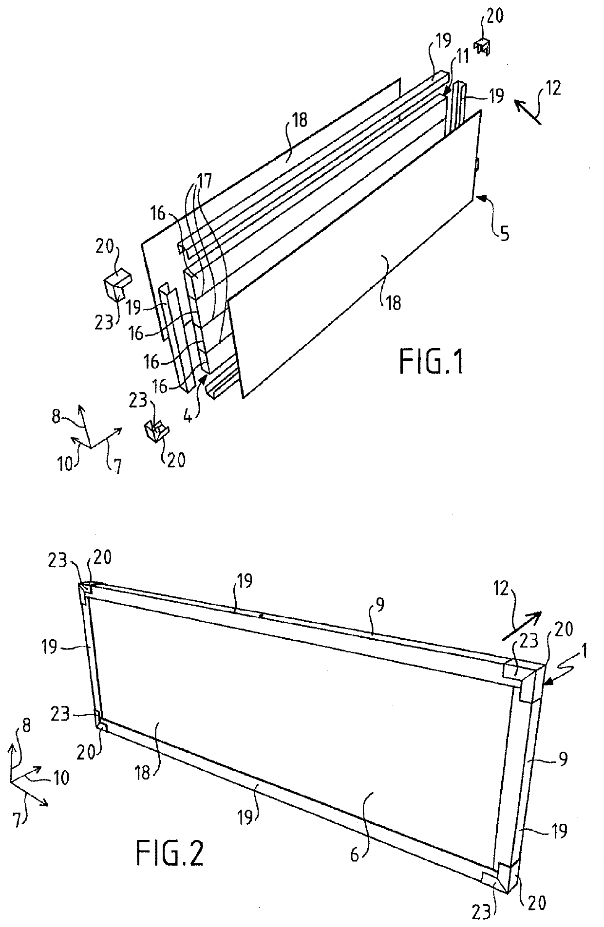
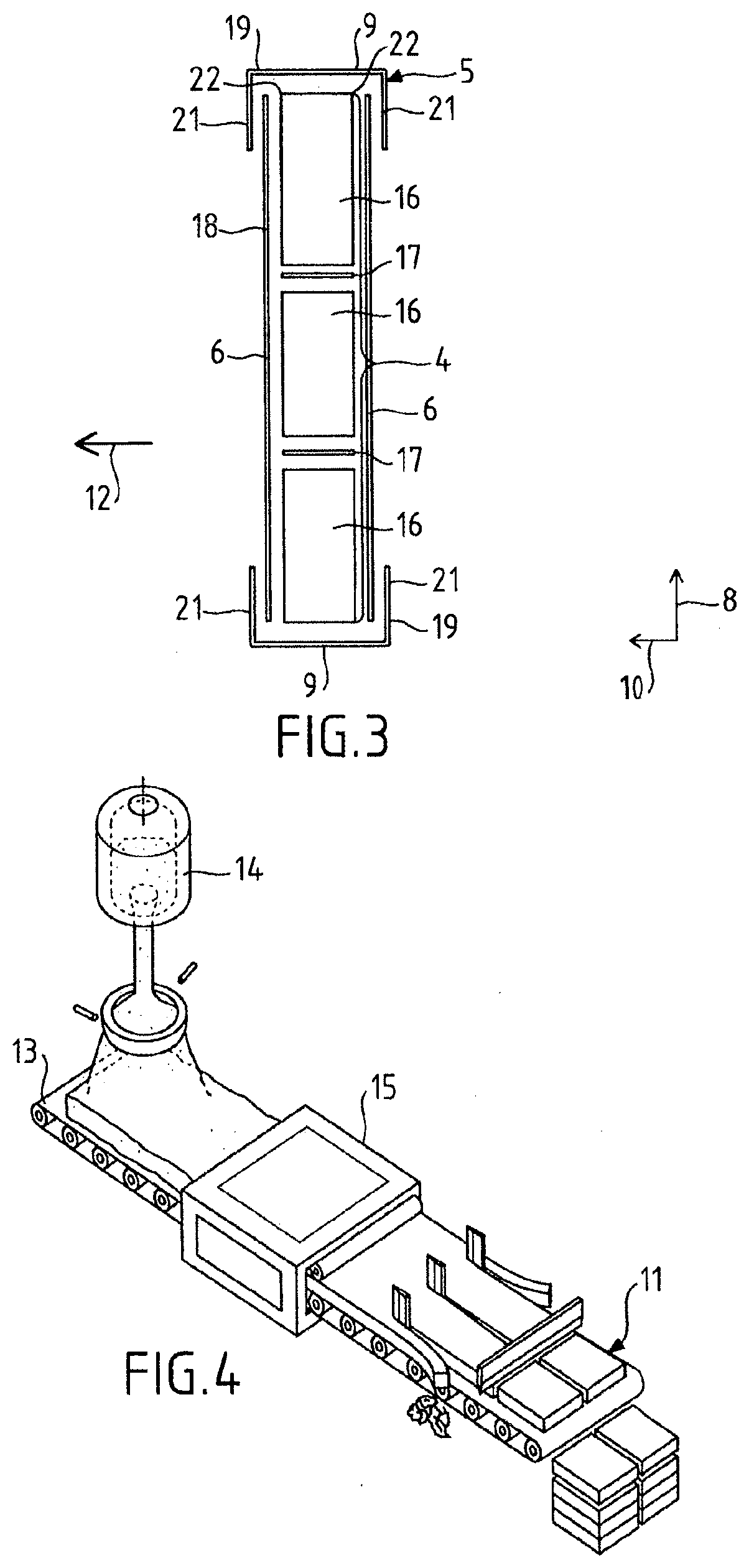

Image

  • Sealed and thermally insulating tank having inter-panel insulating inserts
  • Sealed and thermally insulating tank having inter-panel insulating inserts
  • Sealed and thermally insulating tank having inter-panel insulating inserts

Examples


Embodiment Construction

[0126]A sealed and thermally insulating tank for storing and transporting a cryogenic fluid, for example liquefied natural gas (LNG) comprises a plurality of tank walls each having a multilayer structure.

[0127]Such sealed and thermally insulating tank walls exhibit, from the outside to the inside of the tank, a secondary thermally insulating barrier resting against a bearing structure, a secondary sealing membrane resting against the secondary thermally insulating barrier, a primary thermally insulating barrier resting against the secondary sealing membrane and a primary sealing membrane intended to be in contact with the liquefied gas contained in the tank.

[0128]The bearing structure may notably be a self-supporting metal sheet or, more generally, any type of rigid partition exhibiting suitable mechanical properties. The bearing structure may notably be formed by the hull or the double hull of a ship. The bearing structure comprises a plurality of walls defining the overall shape o...


PUM

PropertyMeasurementUnit
thicknessaaaaaaaaaa
densityaaaaaaaaaa
densityaaaaaaaaaa

Abstract

The invention relates to a sealed and thermally insulating tank wall comprising a thermally insulating barrier defining a support surface for a sealing membrane, the thermally insulating barrier comprising two adjacent insulating panels jointly delimiting an inter-panel space, the tank wall further comprising an insulating insert arranged in the inter-panel space so as to fill the inter-panel space, the insulating insert comprising an insulating core at least partially covered by a wrapper, the insulating core comprising layered glass wool, the layered glass wool comprising laps of fibers superposed in a direction of layering, the insulating insert being arranged in the inter-panel space in such a way that the direction of layering of the layered glass wool is parallel to a widthwise direction of the inter-panel space.

Description

TECHNICAL FIELD[0001]The invention relates to the field of sealed and thermally insulating tanks with membranes. In particular, the invention relates to the field of sealed and thermally insulating tanks for storing and / or transporting low-temperature liquids such as tanks for transporting liquefied petroleum gas (also referred to as LPG) at, for example, a temperature of between −50° C. and 0° C., or for transporting liquefied natural gas (LNG) at around −162° C. at atmospheric pressure. These tanks can be installed on land or on a floating structure. In the case of a floating structure, the tank may be intended for transporting liquefied gas or for receiving liquefied gas used as fuel for the propulsion of the floating structure.TECHNICAL BACKGROUND[0002]A wall structure for creating the planar wall of a sealed and thermally insulating tank has been described, for example in document FR2724623 or document FR2599468. Such a tank wall comprises a multilayered structure comprising, f...

Claims


Application Information

Patent Timeline
Patent Type & Authority Applications(United States)
IPC IPC(8): F17C3/02B63B25/16B63B27/34
CPCF17C3/027B63B25/16B63B27/34F17C2201/0157F17C2203/035F17C2203/0358F17C2209/227F17C2221/033F17C2223/0161F17C2260/033F17C2270/0107F17C2201/052F17C2209/238F17C2223/033F17C2250/0636B63B27/24F17C3/08
Inventor DE COMBARIEU, GUILLAUMEMOREL, BENOÎTLE BIHAN, RONANCAPDEVILLE, JEAN-DAMIENGIMBERT, CHARLESPRUNIER, RAPHAËL
Owner GAZTRANSPORT & TECHNIGAZ
Learn More