
Rotation assist tool and assist-attached rotation tool

Pending Publication Date: 2022-11-17
FREEPOWER INNOVATIONS CO LTD
View PDF0 Cites 0 Cited by
  • Summary
  • Abstract
  • Description
  • Claims
  • Application Information

AI Technical Summary

Benefits of technology

The patent describes a rotation assist tool that reduces the energy required to start rotating an object. It does this by using an elastically deformable body that stores energy during initial movement and then converts it into rotational energy to reduce the load on the object. This also helps to stabilize the rotation and prevent fluctuations in the output energy. The tool can be attached to a rotating tool for easy use.

Problems solved by technology

Therefore, there is a problem that the torsion coil spring is easily damaged due to the repeated alternating load.
Additionally, there is also a problem that the rotation of the output shaft is not easily transmitted to the screwdriver bit, the force to loosen the screw becomes weakened, and workability is reduced, since the torsion coil spring is twisted and deformed in the direction of increasing the outer diameter thereof when removing (loosening) the screw.

Method used


Image

  • Rotation assist tool and assist-attached rotation tool
  • Rotation assist tool and assist-attached rotation tool
  • Rotation assist tool and assist-attached rotation tool

Examples


first embodiment

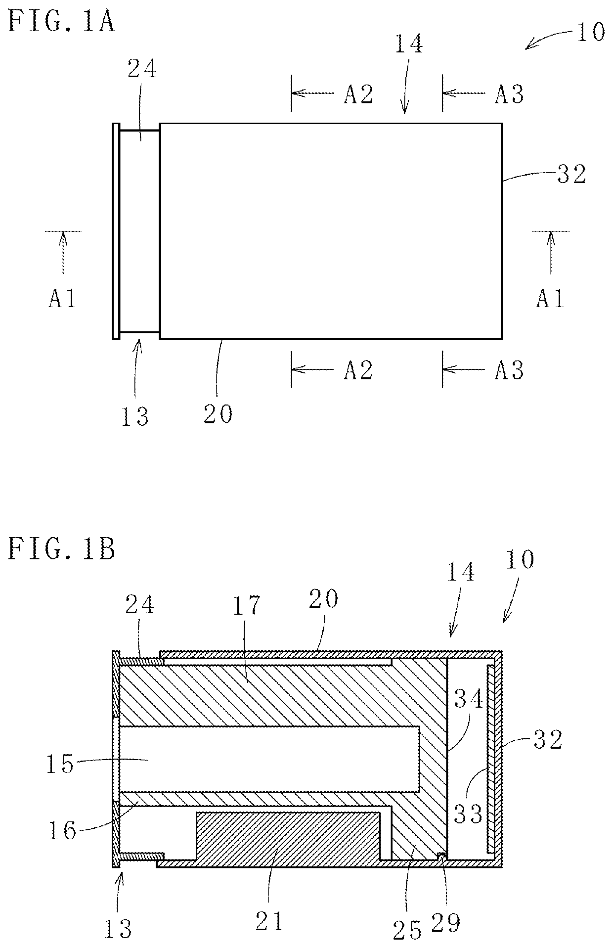
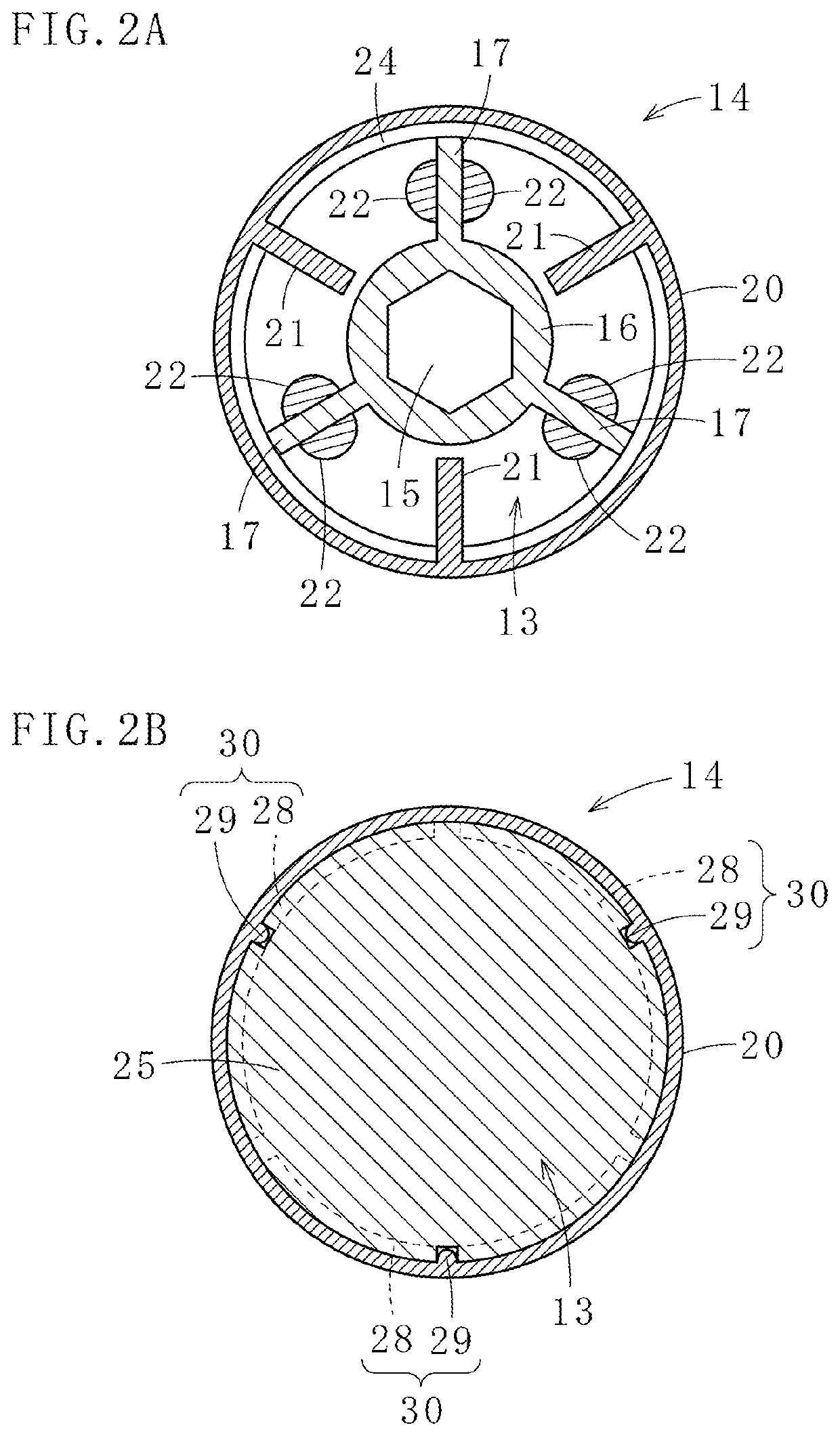
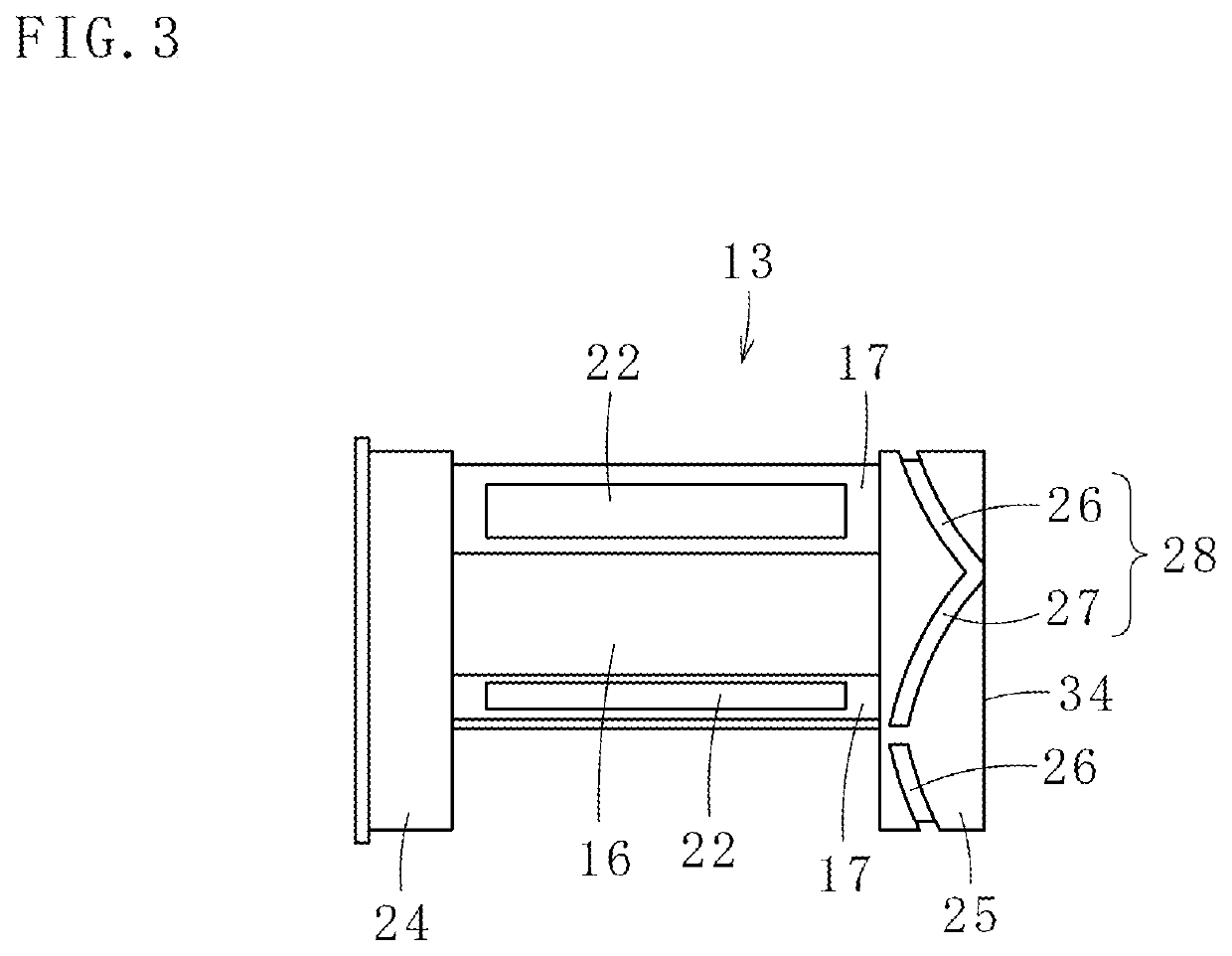
[0092]A rotation assist tool 10 according to the present invention illustrated in FIGS. 1A, 1B, 2A, 2B, and 3 is attached to the base side of a rotary shaft 12 having an output unit 11 similar to a flat-bladed screwdriver on the front side of the rotary shaft 12, and efficiently transmits the input energy to the rotary shaft 12 and output as illustrated in FIGS. 4A, 4B, 5A and 5B.

[0093]As illustrated in FIGS. 1, 2, 4 B, and 5, the rotation assist tool 10 has a first rotating body 13 and a second rotating body 14 held by the first rotating body 13 so as to be able to rotate in the forward and reverse directions. Then, as illustrated in FIGS. 1B, 2A, 3, 4B, and 5A, the first rotating body 13 includes a main body portion 16 with a rotary shaft mounting portion 15 for fixing the base side of the rotary shaft 12, and a plurality of (three in this case) first convex portions 17 provided on the outer circumference of the main body portion 16. In this embodiment, the rotary shaft mounting p...

seventh embodiment

[0146]Next, a rotation assist tool 111 according to the present invention will be described with reference to FIGS. 24, 25A, and 25B.

[0147]The rotation assist tool 111 according to the seventh embodiment of the present invention illustrated in FIGS. 24, 25A, and 25B is attached to the base side of a rotary shaft 112 of an existing bicycle.

[0148]As illustrated in FIG. 24, the rotary shaft 112 is rotatably held by a shaft support portion 113 provided on a frame of the bicycle (not illustrated), and left and right crank arms 114 and 115 are respectively attached to the front side and the base side of the rotary shaft 112 with a phase difference of 180 degrees. Then, a pedal (not illustrated) is rotatably provided on the front side of each of the crank arms 114 and 115, and when the bicycle user (driver) pedals, the rotary shaft 112 together with the crank arms 114 and 115 rotates. Here, an insertion protrusion 112a having a quadrangular cross section is formed on the base side of the r...


PUM


Abstract

Provided are a rotation assist tool 10 attached to a base side of a rotary shaft 12 having an output unit 11 on a front side thereof and a assist-attached rotation tool 31 including the rotation assist tool 10. The rotation assist tool 10 has a first rotating body 13; a second rotating body 14 that is held by the first rotating body 13 to be rotatable in forward and reverse directions; and at least one elastically deformable body 22 that is elastically deformed as the first rotating body 13 and the second rotating body 14 rotate relative to each other, and transmits rotation between the first rotating body 13 and the second rotating body 14, wherein the base side of the rotary shaft 12 is fixed to the first rotating body 13.

Description

TECHNICAL FIELD[0001]The present invention relates to a rotation assist tool capable of efficiently utilizing rotational energy input from the outside and an assist-attached rotation tool provided with the rotation assist tool.BACKGROUND ART[0002]Instead of conventional manual screwdrivers, electric screwdrivers are used at construction sites and the like in recent years in order to shorten work time and improve work efficiency, and to reduce the burden on operators and save labor.[0003]The electric screwdrivers are mainly used for tightening screws at construction sites and the like. It is known that by connecting the output shaft of the motor and the screwdriver bit via a torsion coil spring, the impact caused by the reaction at the time of tightening the screw can be alleviated and the tightening torque of the screw can be stabilized. However, the electric screwdriver is used not only for tightening the screw but also for removing it, and the screwdriver bit rotates in forward an...

Claims


Application Information

Patent Timeline
IPC IPC(8): F16D3/12
CPCF16D3/12B25B21/00B25B23/00A47J43/0711F16D3/68B25B23/0042B62M3/00F16D3/66B62M1/105B62M1/36B62M9/10B25B21/007A47J43/082
Inventor HAMAMOTO, YOICHIRO
Owner FREEPOWER INNOVATIONS CO LTD
Learn More