Oxygen concentration detecting apparatus

a detection apparatus and oxygen technology, applied in the direction of instruments, material electrochemical variables, electric control, etc., can solve the problems of high cost, heavy degraded control precision of air-fuel ratio control systems, and conventional ar

Inactive Publication Date: 2000-01-04
DENSO CORP
View PDF8 Cites 30 Cited by
  • Summary
  • Abstract
  • Description
  • Claims
  • Application Information

AI Technical Summary

Problems solved by technology

However, since the control precision of the air-fuel ratio control systems is heavily degraded if the reliability of detection of the air-fuel ratio deteriorates, there has been a strong demand for a technology that precisely detects an abnormality of an air-fuel ratio sensor.
However, the conventional art has the following problems.
The aforementioned former technology (Japanese Unexamined Patent Application Publication No. Hei. 1-232143) requires a sensor for detecting the temperature of the air-fuel ratio sensor, and thus has problems of high costs.
The latter technology (Japanese Unexamined Patent Application Publication No. Hei. 3-189350) merely determines whether the target resistance is properly set, and the occasions when this diagnosis technology detects abnormality are substantially limited to the occasions when the battery or the sensor has been replaced.
Thus, this technology does not make a determination regarding the reliability of the oxygen sensor.

Method used


Image

  • Oxygen concentration detecting apparatus
  • Oxygen concentration detecting apparatus
  • Oxygen concentration detecting apparatus

Examples


first embodiment

the present invention wherein the oxygen concentration detecting apparatus of the present invention is embodied in an air-fuel ratio control apparatus of an automotive internal combustion engine will be described with reference to the accompanying drawings.

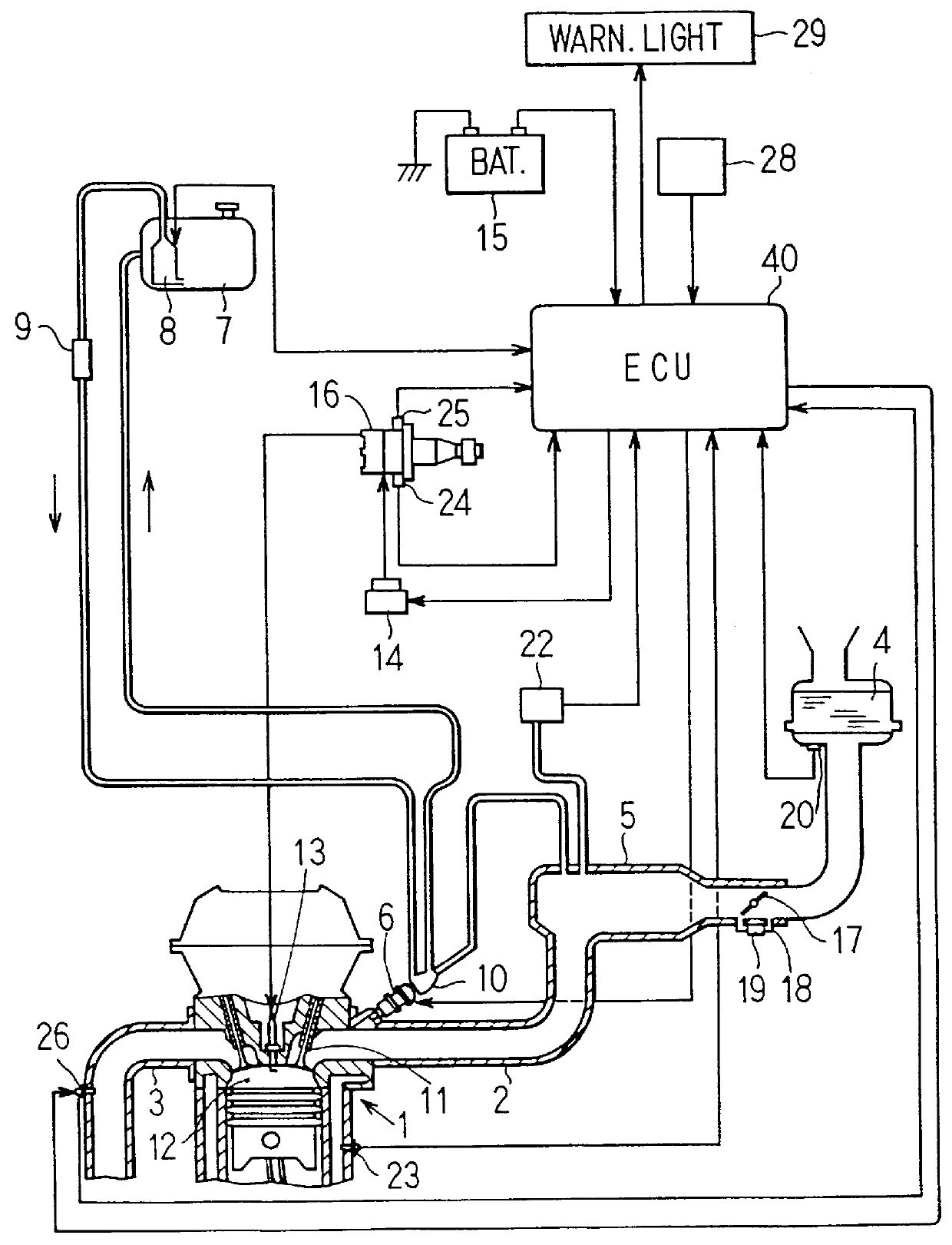
FIG. 1 schematically illustrates the overall construction of the air-fuel ratio control apparatus of the internal combustion engine according to the first embodiment of the present invention. Referring to FIG. 1, a four-cylinder spark-ignition type gasoline internal combustion engine (hereinafter, referred to as "engine") 1 is connected to an intake pipe 2 and an exhaust pipe 3. An air cleaner 4 is provided in a most upstream portion of the intake pipe 2. A surge tank 5 is provided near the middle of the intake pipe 2. Disposed upstream from the surge tank 5 is a throttle valve 17 that is operated responsive to the depression of an accelerator pedal (not shown). A bypass passage 18 bypassing the throttle valve 1 is provided with a...

second embodiment

A second embodiment will be described mainly by referring to the features distinguishing this embodiment from the first embodiment. According to the second embodiment, the CPU 48a provided in the microprocessor 48 constitutes the heater control means, the fuel amount varying means and the sensor diagnostic means in the appended claims. FIG. 10 shows a sensor diagnosis routine according to the second embodiment.

In step 501 in FIG. 10, the CPU 48a determines whether preconditions for the sensor diagnosis have been established. The determination regarding the preconditions in step 501 corresponds to steps 301-307 in FIG. 8. In step 502, the CPU 48a determines whether the air-fuel ratio feedback is being performed. If either step 501 or step 502 makes a negative determination, the CPU 48a ends this routine. If both step 501 and step 502 make an affirmative determination, the CPU 48a proceeds to step 503.

In step 503, the CPU 48a stores the limit current Ip presently detected by the senso...

third embodiment

A third embodiment will be described. While the first and second embodiments open-loop control the heater 33 of the oxygen sensor 26, the third embodiment controls the heater 33 with feedback of the element temperature. According to this embodiment, the CPU 48a provided in the microprocessor 48 constitutes the element resistance detecting means, the heater power supply control means and the sensor diagnostic means in the appended claims.

FIGS. 12A-12D show timing charts indicating heater control according to the third embodiment. More precisely, the timing charts indicate the operation of the heater control performed from the starting of energization of the heater 33 in response to the starting of the engine 1 until sufficient activation of the oxygen sensor 26. According to this embodiment, the heater control can be divided into four modes (1)-(4) as indicated in FIGS. 12A-12D, in view of the different purposes and control methods. These control modes will be described in sequence. ...


PUM

PropertyMeasurementUnit
surface areaaaaaaaaaaa
temperatureaaaaaaaaaa

Abstract

An oxygen concentration detecting apparatus precisely and easily performs diagnosis of a limit current type oxygen sensor. The limit current type oxygen sensor has an oxygen concentration detecting element for outputting limit current proportional to the oxygen concentration and a heater for heating the detecting element. A CPU of a microcomputer controls energization of the heater to activate the oxygen sensor. The CPU calculates element resistance based on the voltage applied to the oxygen sensor and the current detected in the sensor. In a sensor diagnosis routine, the CPU determines whether preconditions for the diagnosis have been met. If all the preconditions have been met, the CPU executes the diagnosis. That is, the CPU determines whether the element resistance is within a predetermined range. If it is below the range, the CPU determines that the sensor has high element temperature abnormality. If the element resistance is above the range, the CPU determines that the sensor has low element temperature abnormality.

Description

The present application is related to and claims priority from Japanese Patent Application No. Hei. 7-76338, incorporated herein by reference.1. Field of the InventionThe present invention relates to an oxygen concentration detecting apparatus having a limit current type oxygen sensor comprising an oxygen concentration detecting element that outputs limit current proportional to oxygen concentration and a heater for heating the detecting element and, more particularly, to an oxygen concentration detecting apparatus that checks for abnormality of the limit current type oxygen sensor.2. Description of Related ArtMany modern air-fuel ratio control systems use limit current type oxygen sensors (oxygen concentration detectors). In such a system, the oxygen concentration detected by the air-fuel ratio sensor is inputted to a microcomputer to calculate an air-fuel ratio, and the microcomputer performs air-fuel ratio feedback control based on the calculated air-fuel ratio. The control syste...

Claims


Application Information

Patent Timeline
Patent Type & Authority Patents(United States)
IPC IPC(8): F02D41/14G01N27/417G01N27/41F02D41/22F02D45/00G01N27/26G01N27/406
CPCF02D41/1455F02D41/1494F02D41/1495G01N27/4067G01N27/4175F02D41/1456
Inventor SAGISAKA, YASUOYAMASHITA, YUKIHIRO
Owner DENSO CORP
Why Eureka
Try Eureka