Low-noise SQUID

a low-noise, squid technology, applied in the direction of super-conductive devices, magnetic measurements, magnetic field measurement, etc., can solve the problems of low-t.sub.c squids, high cost and cumbersome use, and low-t.sub.c squids that are expensive and cumbersome to use, etc., to achieve low 1/f noise and no loss in signal pick-up capability or magnetic field sensitivity.

Inactive Publication Date: 2000-02-08
RGT UNIV OF CALIFORNIA
View PDF2 Cites 42 Cited by
  • Summary
  • Abstract
  • Description
  • Claims
  • Application Information

AI Technical Summary

Benefits of technology

It is an object of this invention to provide high-T.sub.C superconducting devices, for example SQUIDs, that exhibit very low 1 / f noise when cooled and operated, in the presence of a magnetic field. Since cooling the devices is necessary for their operation, all future reference to device operation includes the cooling step. It is a further object of the present invention to provide low-noise high-T.sub.C SQUIDS in which there is no loss in signal pick-up capability or magnetic-field sensitivity. The present invention is useful for SQUIDs having a single superconducting layer and for SQUIDs having multiple superconducting layers.

Problems solved by technology

A SQUID's usefulness is limited primarily by its intrinsic noise, the ability to efficiently couple a signal to it, and by the ability to read out a signal.
However the low temperature requirement, necessitating liquid helium, makes low-T.sub.C SQUIDs expensive and cumbersome to use.
Unfortunately, however, in high-T.sub.C SQUIDs the level of 1 / f noise tends to be impractically high, particularly when cooled and operated in the presence of a magnetic field, even one as small as the Earth's ambient magnetic field, which is about 50 .mu.T.
Excess noise has been a serious limitation for SQUID-based devices.
First, there is ambient noise arising from a variety of sources, such as power lines or electrical appliances, in the environment.
Second, there is noise that arises from magnetic flux vortices penetrating a superconducting film as it is cooled in a static ambient magnetic field.

Method used


Image

  • Low-noise SQUID
  • Low-noise SQUID
  • Low-noise SQUID

Examples


example 1

Threshold Magnetic Field as a Function of Film Width in SQUIDs Having Narrow Bodies Comprising a Single Continuous Loop.

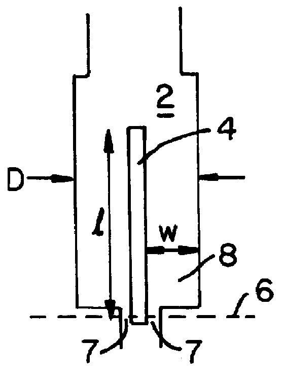
Nine SQUIDs configured like the one shown in FIG. 5 were investigated on a bicrystal. Seven of the nine showed the behavior displayed in FIG. 5. The other two exhibited a rather different behavior in which flux noise increased linearly with B. Presumably vortices, were not excluded from these SQUIDs, even when only very small ambient magnetic fields were present during cooling. It could be that variation in film quality, particularly at the edges, contributes to the differences in behavior.

FIG. 5 shows the flux noise as a function of magnetic field for inventive SQUIDs having different body widths, D, and superconducting film widths, w. Two inventive SQUIDs having a body width of 30 .mu.m and w of 13 .mu.m are designated with the symbols + and .quadrature.. Flux noise begins to increase at a threshold ambient magnetic field, B, equal to about 20 .mu.T. A third inve...

example 2

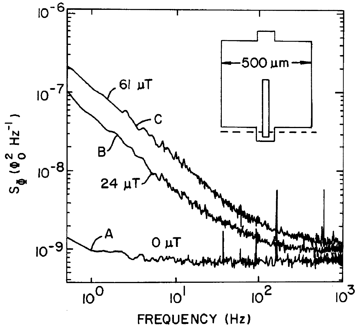
Noise Spectra as a Function of Ambient Magnetic Field During Device Cooling in Inventive Narrow Body SOUIDs

Device 8 (w=13 .mu.m) was cooled in the presence of a magnetic field and the flux noise was measured as a function of frequency. The measurements were repeated for three different ambient magnetic fields, 0 .mu.T, 19.5 .mu.T, and 23.4 .mu.T. The four resulting curves were similar to those shown in FIG. 3. For B=0, the curve was essentially flat at the intrinsic thermal noise level.

When the device was cooled in a field of B=19.5 .mu.T, the noise above about 5 Hz was indistinguishable from the flat zero-field response. Below about 5 Hz the noise increased slightly indicating onset of flux vortex entry.

When the device was cooled in a field of B=23.4 .mu.T, the flux noise, at 1 Hz, increased by about a factor of 3 over the zero-field value. The power spectrum below about 200 Hz scales approximately as 1 / f.sup.0.4 ; a significantly more shallow slope than typically seen in conventio...

example 3

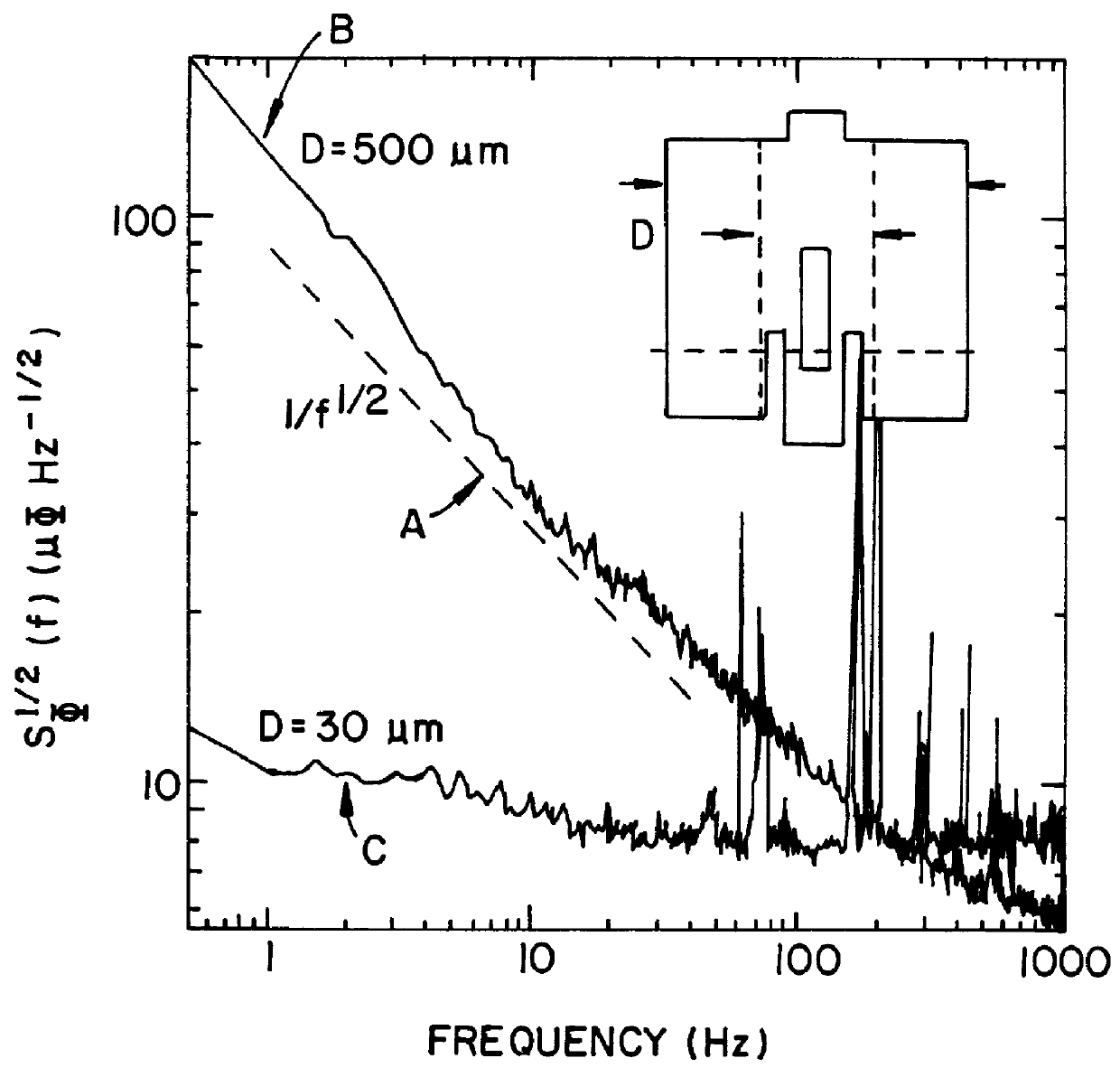
Directly Coupled Magnetometers

On a separate bicrystal, ten small directly coupled magnetometers were fabricated. The magnetometers were comprised of a SQUID coupled to a pickup loop made of a 4 .mu.m wide film strip laid out in a 1.8 mm by 3.8 mm rectangle. The SQUIDs were made having a body width, D, between about 12 .mu.m and about 30 .mu.m. The effective areas of these magnetometers were comparable to those of conventional large-washer SQUIDs having an outside diameter of about 500 .mu.m.

In FIG. 6, the geometry of devices 10-12 are shown schematically in the inset. The graph shows the flux noise on the ordinate and the magnetic field (in .mu.T) that was applied during cooling of the magnetometer on the abscissa. Measurements obtained from device 10 are denoted with the symbol X, device 11 with the symbol +, and device 12 with the symbol .quadrature..

The graph in FIG. 6 shows flux noise vs. B for these devices. For D=30 .mu.m (w=13 .mu.m), the noise increases at about 20 .mu.T (as...


PUM


Abstract

The present invention comprises a high-transition-temperature superconducting device having low-magnitude low-frequency noise-characteristics in magnetic fields comprising superconducting films wherein the films have a width that is less than or equal to a critical width, wC, which depends on an ambient magnetic field. For operation in the Earth's magnetic field, the critical width is about 6 micrometers ( mu m). When made with film widths of about 4 mu m an inventive high transition-temperature, superconducting quantum interference device (SQUID) excluded magnetic flux vortices up to a threshold ambient magnetic field of about 100 microTesla ( mu T). SQUIDs were fabricated having several different film strip patterns. When the film strip width was kept at about 4 mu m, the SQUIDs exhibited essentially no increase in low-frequency noise, even when cooled in static magnetic fields of magnitude up to 100 mu T. Furthermore, the mutual inductance between the inventive devices and a seven-turn spiral coil was at least 85% of that for inductive coupling to a conventional SQUID.

Description

I. BACKGROUND OF THE INVENTION1. Field of the InventionThis invention relates generally to superconducting quantum interference devices (SQUIDs) and more specifically to high-transition-temperature, low-noise SQUIDs.2. Description of Related ArtSuperconducting quantum interference devices (SQUIDs) are used to detect magnetic flux. They transduce magnetic flux into voltage. The SQUID is used for a range of applications in which low level physical phenomena are readily converted to magnetic flux. For example, current, voltage, magnetic field, and magnetic field gradient can all be measured via magnetic flux. High transition temperature (high-T.sub.C) SQUIDs are those made with materials having a transition temperature above the boiling point of liquid nitrogen (77 K). Low-transition temperature (low-T.sub.C) SQUIDs are those made with materials having a transition temperature below the boiling point of liquid nitrogen (77 K). A SQUID's usefulness is limited primarily by its intrinsic ...

Claims


Application Information

Patent Timeline
Patent Type & Authority Patents(United States)
IPC IPC(8): G01R33/035
CPCG01R33/0354Y10S505/846
Inventor DANTSKER, EUGENECLARKE, JOHN
Owner RGT UNIV OF CALIFORNIA
Why Eureka
Try Eureka