Satellite signal splitter

a satellite signal and splitter technology, applied in the field of satellite signal splitter, can solve the problem of remarkably laborious indoor wiring work

Inactive Publication Date: 2000-02-08
MASPRODENKOH KK
View PDF5 Cites 79 Cited by
  • Summary
  • Abstract
  • Description
  • Claims
  • Application Information

AI Technical Summary

Problems solved by technology

Therefore, indoor wiring works are remarkably laborious.
Therefore, there is a problem that a switching unit must be separately provided on the terminal side for receiving the polarized-wave switching signal (of 11V or 15V) from the CS tuner and switching between the input of the vertically polarized-wave signal and the input of the horizontally polarized-wave signal into the CS tuner.

Method used


Image

  • Satellite signal splitter
  • Satellite signal splitter
  • Satellite signal splitter

Examples


Embodiment Construction

An embodiment of the invention is described with reference to the accompanying drawings.

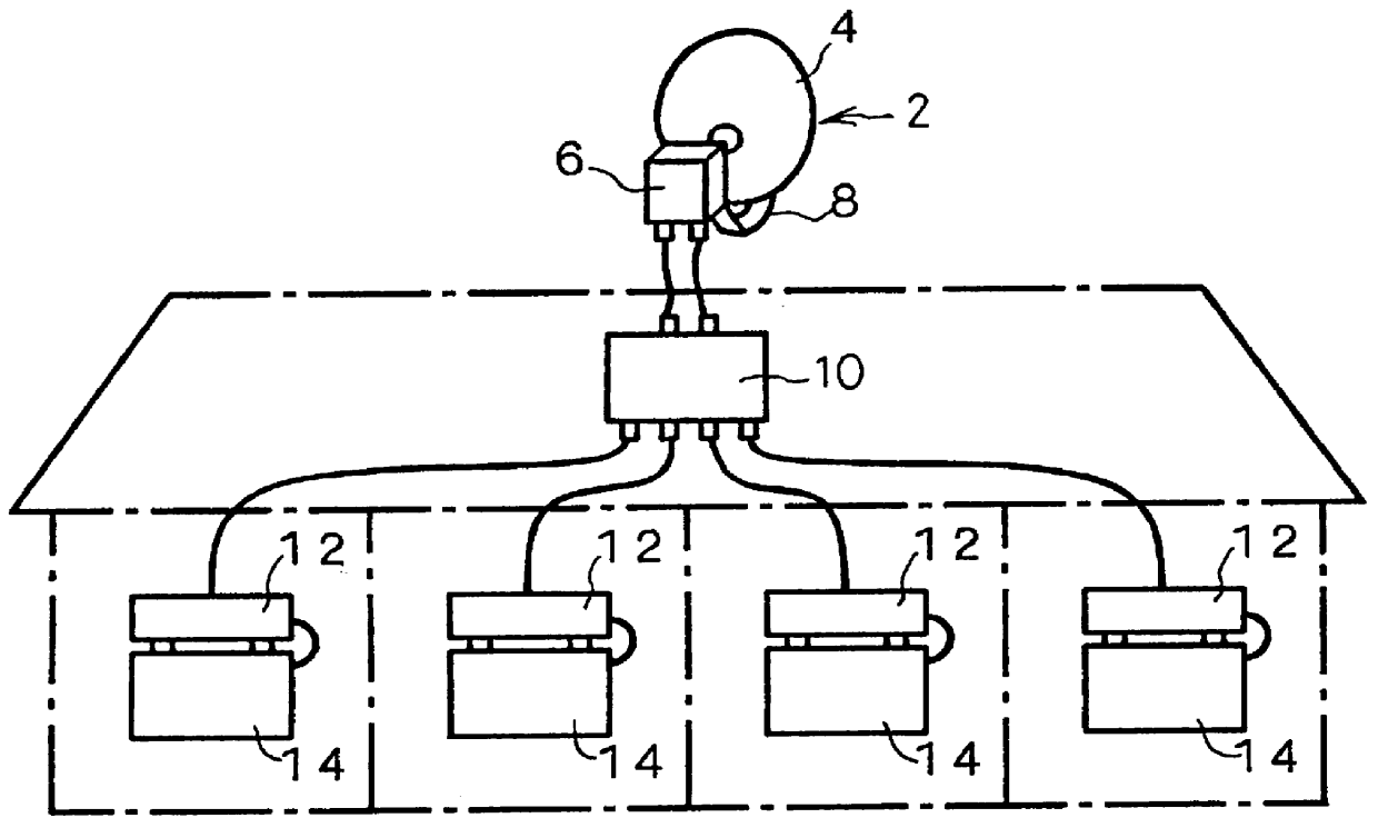
First, FIG. 2 is a block diagram showing an entire constitution of a common receiving system provided with a satellite signal splitter (hereinafter, referred to just as the splitter) to which the invention is applied.

[0030]

As shown in FIG. 2, the common receiving system of the embodiment is provided with a receiving antenna 2 which is an off-set type of parabola antenna for receiving two orthogonal polarized waves transmitted from a communication satellite. The receiving antenna 2 is constituted of a reflective mirror 4 and a receiving portion 6 disposed on a focal position of the reflective mirror 4 via a support arm 8. The receiving portion 6, called a two-output type of converter, is provided in a known manner with a pair of converter circuits which receive and amplify the electric waves transmitted from the communication satellite and collected on the reflective mirror 4, independently select...


PUM


Abstract

A satellite signal splitter is proposed which can transmit a received signal of a desired polarized wave with one cable to each terminal side when transmitting to plural terminal sides the received signals from a satellite receiving antenna which emits the received signals of a vertically polarized wave and a horizontally polarized wave. The vertically and horizontally polarized-wave received signals transmitted to input terminals 22V and 22H are split into four by splitting circuits 26V and 26H, respectively. The four split signals are transmitted to switching circuits 28a to 28d. In the switching circuits 28a to 28d, in accordance with a voltage level (11V or 15V) of a polarized-wave switching signal transmitted from terminal units connected to output terminals 24a to 24d, either the vertically or horizontally polarized-wave signal is selected and emitted from the output terminals 24a to 24d. Also, the polarized-wave switching signal (11V or 15V) is transmitted via a voltage synthesizing portion 30, choke coils LV, LH and the like from the input terminals 22V and 22H to a corresponding receiving portion of a receiving antenna.

Description

[0001]1. Technical Field of the InventionThe present invention relates to a preferable satellite signal splitter which splits received signals transmitted from a satellite receiving antenna, which is for receiving electric waves of two orthogonal polarized waves transmitted from a communication satellite and emitting received signals of the polarized waves, to plural terminal units.[0002]2. Prior Art and Problem to be Solved by the InventionAs a satellite receiving antenna for receiving two orthogonal polarized waves from a communication satellite, a heretofore known antenna is provided with a receiving portion for splitting electric waves of two orthogonal polarized waves into a vertically polarized-wave signal and a horizontally polarized-wave signal, converting the vertically polarized-wave signal and the horizontally polarized-wave signal into received signals having a predetermined frequency band, respectively, and emitting the converted received signals.[0003]To transmit the r...

Claims


Application Information

Patent Timeline
Patent Type & Authority Patents(United States)
IPC IPC(8): H04N7/20H04B1/18H04N5/00H04N21/647
CPCH04N7/20
Inventor MATSUBARA, HIROSHI
Owner MASPRODENKOH KK
Why Eureka
Try Eureka