Internal combustion engine misfire detection with engine acceleration and deceleration correction during a repetitive misfire condition

a technology of misfire detection and engine acceleration, applied in the direction of machines/engines, electrical control, instruments, etc., can solve the problems of conventional misfire detection apparatus not being able to detect a misfire occurrence, the technique has almost completely cancelled the detection of errors caused, and the problem of problems persisting

Inactive Publication Date: 2000-02-08
DENSO CORP
View PDF8 Cites 60 Cited by
  • Summary
  • Abstract
  • Description
  • Claims
  • Application Information

AI Technical Summary

Problems solved by technology

This technique has almost completely canceled detection errors caused by the dispersion of rotational speeds between cylinders.
However, according to the above-mentioned related art, problems remain.
For example, the conventional misfire detecting apparatus may not be able to detect an occurrence of misfire caused by a specific pattern.
More specifically, in case of calculating the difference in rotational speed variation for facing cylinders (cylinders separated by 360.degree. CA), occurrence of misfire cannot be detected because, when both facing cylinders are misfiring, rotational variations due to misfires are counterbalanced.
In addition, in case of calculating the difference of rotational speed variation for of the same cylinder (cylinders separated by 720.degree. CA), an occurrence of misfire also cannot be detected because when the same specific cylinder is continuously misfiring, rotational variation due to the misfires are counterbalanced.

Method used


Image

  • Internal combustion engine misfire detection with engine acceleration and deceleration correction during a repetitive misfire condition
  • Internal combustion engine misfire detection with engine acceleration and deceleration correction during a repetitive misfire condition
  • Internal combustion engine misfire detection with engine acceleration and deceleration correction during a repetitive misfire condition

Examples


first embodiment

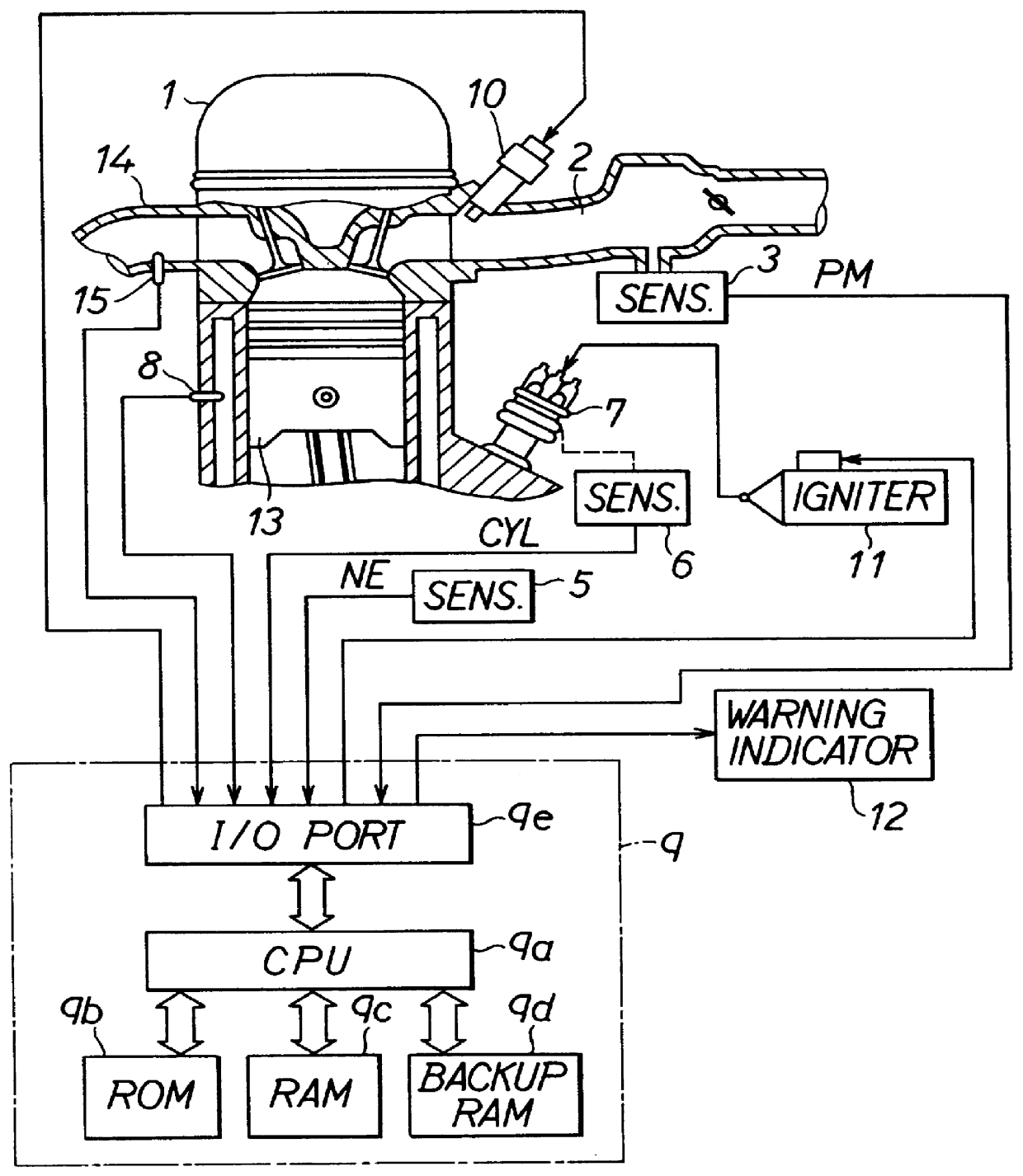
The first embodiment is intended for a V-8 four-stroke type internal combustion engine. That is, as shown in FIG. 1, an internal combustion engine 1 has eight cylinders. Here, the firing order is assumed to be #1.fwdarw.#2.fwdarw.#3.fwdarw.#4.fwdarw.#5.fwdarw.#6.fwdarw.#7.fwdarw.#8 for convenience.

The internal combustion engine 1 is connected to an intake pipe 2 for leading intake air introduced from an air cleaner (not shown) into the engine 1 via the intake pipe 2. In the intake pipe 2, an intake pipe pressure sensor 3 is provided for sensing a pressure PM within the intake pipe 2. The detected pressure PM within the intake pipe 2 is input as one parameter indicative of the operating condition of the internal combustion engine 1 to an electronic control unit (hereinafter, ECU) 9 which will be described later.

Further, in relation to the crankshaft (not shown) of the engine 1, an electromagnetic pickup-type rotational angle sensor 5 generates a rotational signal NE at every predete...


PUM


Abstract

To accurately detect patterns of misfires in an internal combustion engine, misfire is detected by calculating angular speed variation responsive to crankshaft rotation and comparing that with a predetermined misfire reference value. The calculated angular speed variation includes a first elementary term showing rotational variation of two different cylinders and a second correction term showing the rotational variation of the same cylinder separated by one combustion cycle. The elementary term shows how much rotational variation is between the cylinder n and the previous cylinder n-1 due to the occurrence of misfire. In contrast, the correction term shows how much error in the rotational variation is caused in same cylinder (e.g., mainly when accelerating or decelerating).

Description

1. Field of the InventionThe present invention relates to an apparatus for detecting the occurrence of misfire in an internal combustion engine using rotational speed variation of an engine output shaft.2. Description of Related ArtConventionally, as such kinds of an apparatus for detecting the occurrence of misfire in an internal combustion engine, JP-A 4-365958 (U.S. Pat. No. 5,275,037), for example, discloses an apparatus for detecting the occurrence of misfire based on variation of rotational speed (a crank angular speed) between two cylinders which successively make expansion strokes. Generally, in an internal combustion engine, when a misfire occurs during an expansion stroke in one cylinder, the rotational speed at this time, that is, the rotational angular speed of the crankshaft, which is an engine output shaft, decreases. For this reason, the occurrence of misfire in each cylinder can be detected by watching changes in rotational speed.Particularly, in such an apparatus of...

Claims


Application Information

Patent Timeline
Patent Type & Authority Patents(United States)
IPC IPC(8): F02D41/22F02D45/00G01M15/00G01M15/04
CPCF02D41/1498G01M15/11F02D2200/1015
Inventor NAKAYAMA, MASAAKIMUKAI, YASUO
Owner DENSO CORP
Why Eureka
Try Eureka