Gelatinous cushions with buckling columns

a cushion and cushion technology, applied in the field of cushions, can solve the problems of tissue damage and discomfort of a human using the cushion, and achieve the effects of eliminating pressure peaks, not affecting the comfort of users, and maximizing the surface area of the cushioned obj

Inactive Publication Date: 2000-02-22
EDIZONE LC
View PDF132 Cites 260 Cited by
  • Summary
  • Abstract
  • Description
  • Claims
  • Application Information

AI Technical Summary

Benefits of technology

pressure peaks. It is a consequent advantage of the invention that the invented cushion is comfortable and does not tend to constrict blood flow in the tissue of a human being on the cushion, thus being suitable for medical applications and other applications where the object being cushioned may be immobile for long periods of time, such as in automobile seats, furniture, mattresses, and other applications.
It is an object of the invention to provide a cushion that eliminates pressure peaks on an object being cushioned. It is a feature of the invention, as mentioned above, that the invented cushion includes columns which buckle under protuberances on a cushioned object. As a result, the cushioned object is not exposed to pressure peaks.
It is an object of the invention to maximize the surface area of the cushioned object that is in contact with the cushion by permitting the cushioned object to sink deeply into the cushion, without the prior art problem that exterior surfaces of the cushion that are not in the plane in contact with the cushioned object must expand. It is a feature of the invented cushion that the cushion is compressible and that the cushion includes columns within it that can buckle under the weight of the cushioned object. The bottom of the cushion and its outside periphery, not including the surface of the cushion in contact with the cushioned object, may, if desired, be restrained, but the compressibility and bucklability of the cushion will still permit the cushioned object to sink into the cushion. It is an advantage of the invention that a gel cushion is provided which can have a constrained periphery but which will still permit a cushioned object to sink deeply into it.
It is an object of the invention to provide a cushion that elimin...

Problems solved by technology

This action is due to compressibility of the cushion.
Head pressu...

Method used


Image

  • Gelatinous cushions with buckling columns
  • Gelatinous cushions with buckling columns
  • Gelatinous cushions with buckling columns

Examples


embodiment 2301

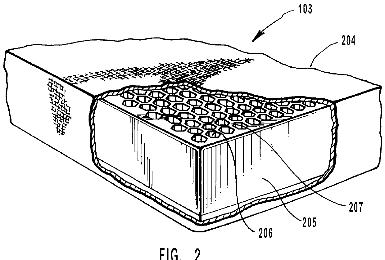
also includes columns 2304, column walls 2305 and an outer periphery 2306. Columns 2304 are formed through cover 2302 and lined with cushioning medium 2302. With reference to FIGS. 23a and 23b, where two adjacent columns 2304a and 2304b are separated only by a thin column wall 2305a (e.g., a column wall having a thickness of only about 0.1 inch or less), the column wall is preferably made from cushioning medium 2302. Where two adjacent columns 2304c and 2304d are separated by a thicker column wall 2305c, the column wall preferably includes a cover 2302 of the first cushioning medium and is filled with second cushioning medium 2303.

The use of multiple cushioning media in cushion 2301 facilitates tailoring of the rebound, pressure absorption, and flow characteristics of the cushion. Compressibility of cushion 2301 also depends upon the amount of spacing between columns and the formulations of the first second cushioning media 2302 and 2303, respectively.

FIGS. 24a and 24b illustrate an...

examples 1 through 14

include various mixtures of SEPTON 4055 (available from Kuraray) ultra high molecular weight polystyrene-hydrogenated poly(isoprene+butadiene)-polystyrene triblock copolymer extended in a plasticizing oil. In addition, the materials of Examples 1 through 14 include very minor amounts of IRGANOX.RTM. 1010 (about 0.03%), IRGAFOS.RTM. 168 (about 0.03%), and colorant (about 0.04%).

The material of each of Examples 1 through 14 was compounded in an ISF 120VL injection molding machine, manufactured by Toshiba Machine Co. of Tokyo, Japan, with a 20:1 (L / D) high mixing single screw manufactured by Atlantic Feed Screw, Inc. of Cayce, S.C. The temperature in the injection molding machine was increased stepwise from the point of insertion to the injection nozzle. At the point of insertion, the temperature was about 270.degree. F. Temperatures along the screw were about 275.degree. F. and about 280.degree. F., with the temperature increasing as the material approached the injection nozzle. The t...

example 1

The material of Example 1 includes eight parts LP 150 mineral oil to one part SEPTON 4055.

In comparison, the material of Chen's patents that has an oil to elastomer ratio of 4:1, which should have higher strength than Applicant's 8:1 material of Example 1, instead exhibits much lower elongation and PSI at failure (i.e., tensile strength) values. The material of Example 1 elongates up to about 2,400%, which is 700% greater elongation than Chen's 4:1, which is capable of only 1700% elongation (See, e.g., '213 Patent, Table I, col. 6, lines 18-38). Likewise, the tensile strength at break of Chen's 4:1 gel is only about 4.times.10.sup.6 dyne / cm.sup.2, or 58 psi. Thus, the 8:1 material of Example 1 is at least three times as strong as Chen's 4:1. This is an unexpectedly good result since the conventional wisdom concerning gels is that more oil results in less strength. Applicant doubled the amount of oil used (8:1 compared to 4:1) but achieved more than three times the tensile strength o...


PUM

PropertyMeasurementUnit
Temperatureaaaaaaaaaa
Percent by massaaaaaaaaaa
Fractionaaaaaaaaaa

Abstract

A cushioning element that has a number of substantially parallel elongate columns which buckle under an appropriate load. The cushioning element may be formed from a soft, easily deformable elastic or visco-elastic cushioning media. As a force is exerted against the cushioning element generally parallel to a column, the cushioning media may compress, and eventually the walls of the column may buckle. This equalizes pressure across the contact area of the object being cushioned.

Description

I. BACKGROUND OF THE INVENTIONA. Field of the InventionThis invention relates to the field of cushions. More particularly, this invention relates to a cushion made of gelatinous elastomer, gelatinous visco-elastomer, or materials with similar characteristics which has hollow columns that compress to provide cushioning and which buckle to relieve pressure peaks.B. The Background ArtIn the prior art, there have been numerous attempts to provide a cushion which achieves comfort by eliminating peak pressure areas and by evenly distributing the cushioning force over a broad surface area. The relevant prior art of which the inventor is aware is categorized and summarized below.1. Foam Cushions: Foam cushions typically include open cell polyurethane foam because of its low cost and light weight. The open cells are, in effect, air bubbles within the polyurethane which can be compressed and from which air can escape when a force, such as the weight of a cushioned object, is placed on the foa...

Claims


Application Information

Patent Timeline
IPC IPC(8): A47C4/54A47C27/14A47C4/00A47C27/08A47C27/00A43B13/04B29C44/50B29C44/58B29C48/08B29C48/11B29C48/30B29C48/32C02F1/28C08K5/00C08K5/01C08L51/00C08L53/00C08L53/02
CPCA43B13/04A47C7/021A47C27/085A47C27/144A47C27/15B29C44/50B29C44/583B29C47/0004B29C47/0028B29C47/12C08K5/0016C08K5/01C08L51/006C08L53/025A47C4/54C08L53/02Y10T428/24331B29C47/884B29C2793/009B29K2105/04B29L2031/60Y10T428/24322Y10S5/909Y10S5/948Y10S5/953C08L2666/02B29C48/022B29C48/11B29C48/9135B29C48/919B29C48/08
Inventor PEARCE, TONY M.
Owner EDIZONE LC
Why Eureka
Try Eureka