Mixing and delivery syringe assembly

Inactive Publication Date: 2000-02-22
PESCADERO BEACH HLDG
View PDF5 Cites 203 Cited by
  • Summary
  • Abstract
  • Description
  • Claims
  • Application Information

AI Technical Summary

Benefits of technology

Another object of the invention is to provide a novel adapter assembly for use with the syringe housing which is easy to

Problems solved by technology

Mixing of powdered pharmaceuticals with the carrier liquid has been accomplished in several ways, many of them being quite crude.
This method is quite tedious and provides substantial opportunities for contamination and error.
This mixing step can be time consuming and hazardous, as for examp

Method used


Image

  • Mixing and delivery syringe assembly
  • Mixing and delivery syringe assembly
  • Mixing and delivery syringe assembly

Examples


Embodiment Construction

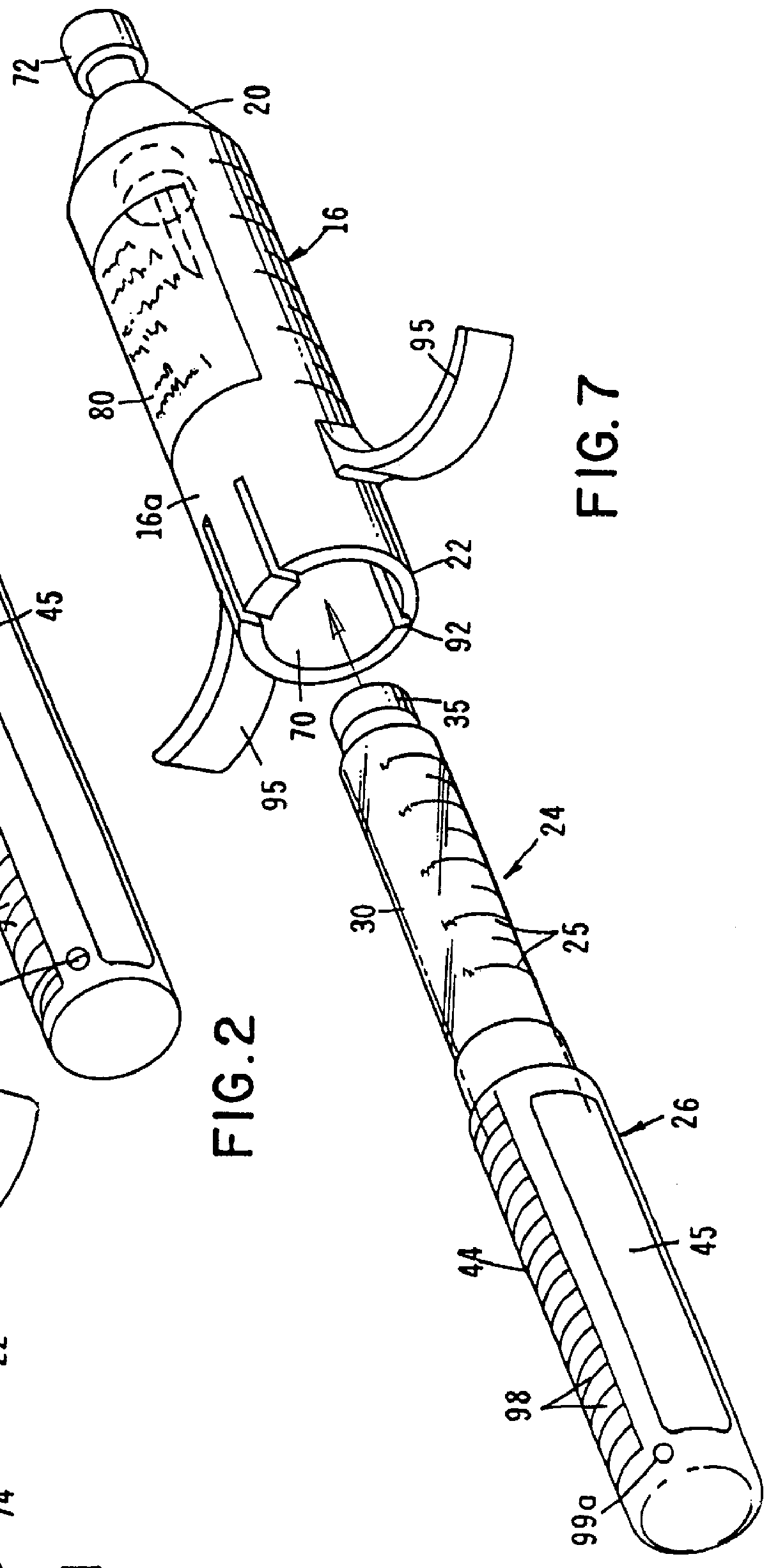
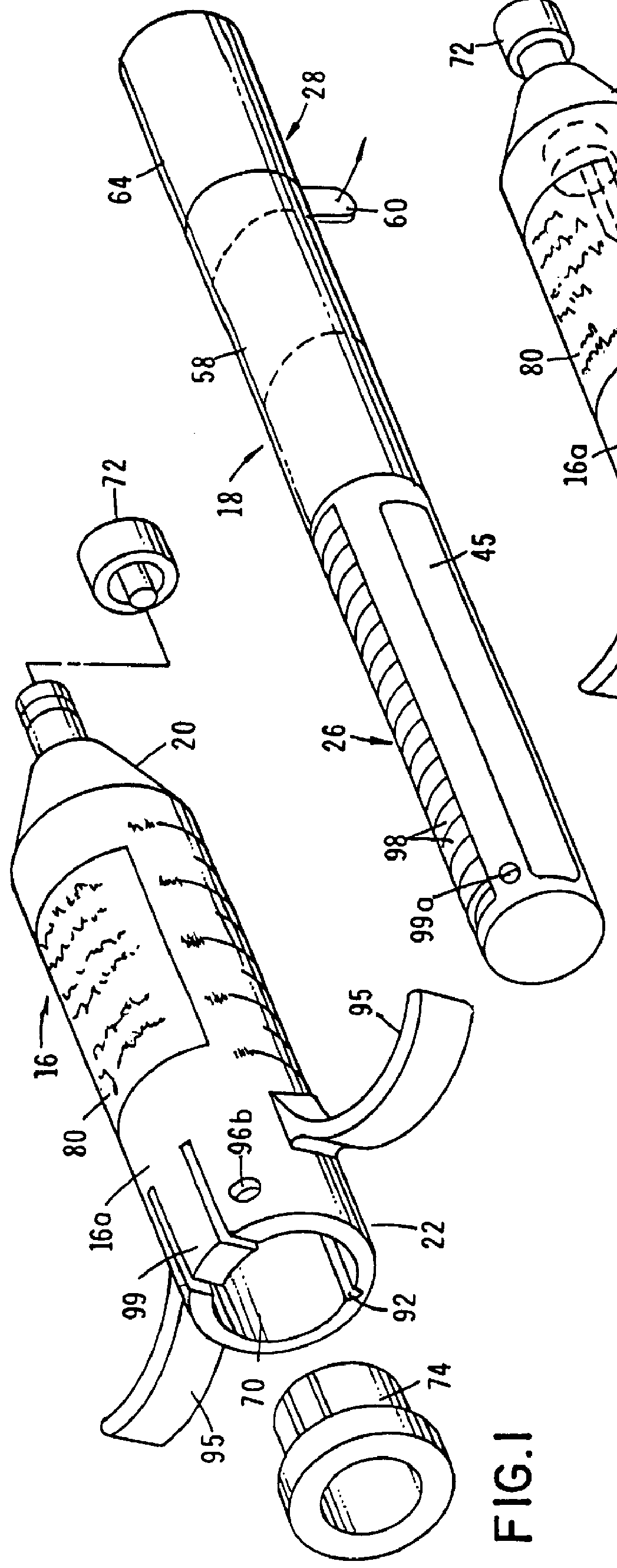
Referring to the drawings and particularly to FIGS. 1 through 3, one form of the apparatus of the present invention is there illustrated. The apparatus here comprises two main assemblies, namely a syringe assembly 16 (FIG. 1) and a fill assembly 18 (FIG. 2) which can be operably mated with the syringe assembly in a manner presently to be described. Syringe assembly 16, the details of construction of which will presently be described, is similar in some respects to the syringe assembly described in Ser. No. 08 / 271,378 and includes a hollow housing 16a having first and second ends 20 and 22.

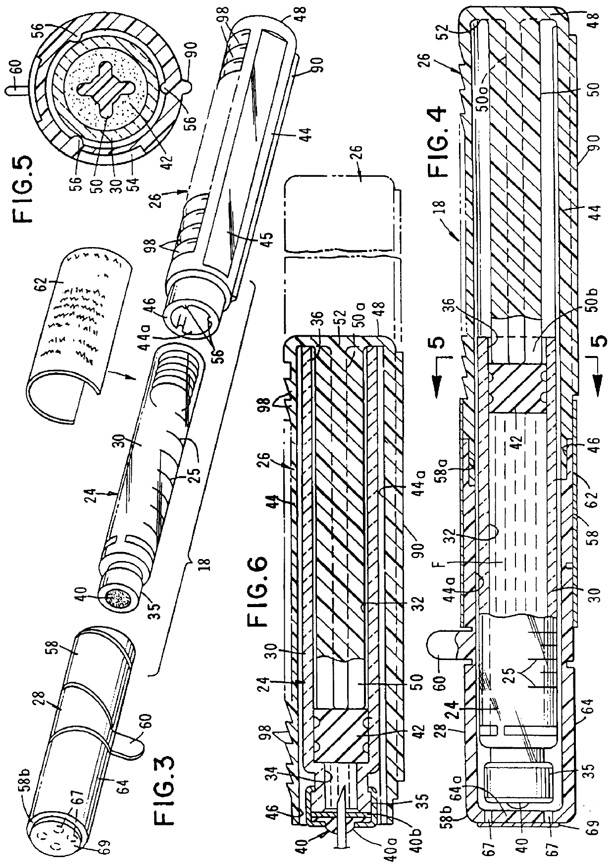
As best seen by referring to FIGS. 2, 3, and 4, the fill assembly portion 18 of the apparatus comprises a container subassembly 24, an adapter subassembly 26, and a cover subassembly 28, the character of which will presently be described. Container subassembly 24 includes a body portion 30, having a fluid chamber 32 for containing an injectable fluid "F" (FIG. 4). Chamber 32 is provided with first ...


PUM


Abstract

A syringe type apparatus which includes a unique fill assembly for use in controllably injecting medicinal fluids into a patient. The filling assembly includes a prefilled vial which is partially received within a novel adapter assembly that functions to operably couple the prefilled vial with the syringe assembly of the apparatus. The body of the prefilled vial is surrounded by a protective covering until immediately prior to mating the assembly with the syringe assembly.

Description

The present invention relates generally to syringes of the character used to administer drugs by injecting them into subcutaneous tissue. More particularly, the invention concerns a syringe of novel design in which a first component, such as a sterilized diluent, can be intermixed with a second component, such as a drug to form a beneficial agent which can be dispensed directly from the syringe.DISCUSSION OF THE INVENTIONHypodermic syringes are commonly used for injecting into a patient beneficial agents, such as drugs in liquid form. Typically, the beneficial agent to be injected is drawn into the syringe from another container, such as a glass vial, bottle or the like having a pierceable, self-sealing stopper. When the beneficial agent, such as a pharmaceutical, is in powder form prior to injection, it must be mixed with a carrier liquid or diluent, such as saline solution, dextrose solution and sterilized water.Mixing of powdered pharmaceuticals with the carrier liquid has been a...

Claims


Application Information

Patent Timeline
IPC IPC(8): A61M5/145A61M5/24A61M5/20A61M5/31A61M5/34A61M5/50
CPCA61M5/14526A61M5/24A61M5/2429A61M5/2448A61M5/20A61M5/2466A61M5/3145A61M5/348A61M5/5013A61M5/502A61M2005/2407A61M2005/247A61M2005/3104A61M2205/273A61M2205/276A61M2209/045
Inventor KRIESEL, MARSHALL S.THOMPSON, THOMAS N.
Owner PESCADERO BEACH HLDG
Why Eureka
Try Eureka