Arrangement in a bulb generator

a bulb generator and arrangement technology, applied in the direction of renewable energy generation, greenhouse gas reduction, magnetic circuit shape/form/construction, etc., can solve the problems of large heat resistance through the bulb wall, often hampered arrangement, etc., to avoid the disadvantage of polluting the water of the river, avoid welding work and expensive materials, and avoid the effect of polluting the water

Inactive Publication Date: 2000-02-22
ALSTOM TECH LTD
View PDF16 Cites 2 Cited by
  • Summary
  • Abstract
  • Description
  • Claims
  • Application Information

AI Technical Summary

Benefits of technology

Further, an object of the present invention is to provide an arrangement wherein welding work and expensive materials are reduced to a minimum, whilst at the same time providing an arrangement having favourable cooling characteristics, and at the same time avoiding the disadvantages related to possible polluted river water.

Problems solved by technology

Such an arrangement is often hampered with problems, inter alia because filters are required due to the quality of the river water.
Even if such a prior art system may operate well, it is hampered with certain weaknesses especially as regards costly extra expenditures including comprehensive welding work, expensive materials, etc., the heat resistance through the bulb wall being relatively large.

Method used


Image

  • Arrangement in a bulb generator
  • Arrangement in a bulb generator
  • Arrangement in a bulb generator

Examples


Embodiment Construction

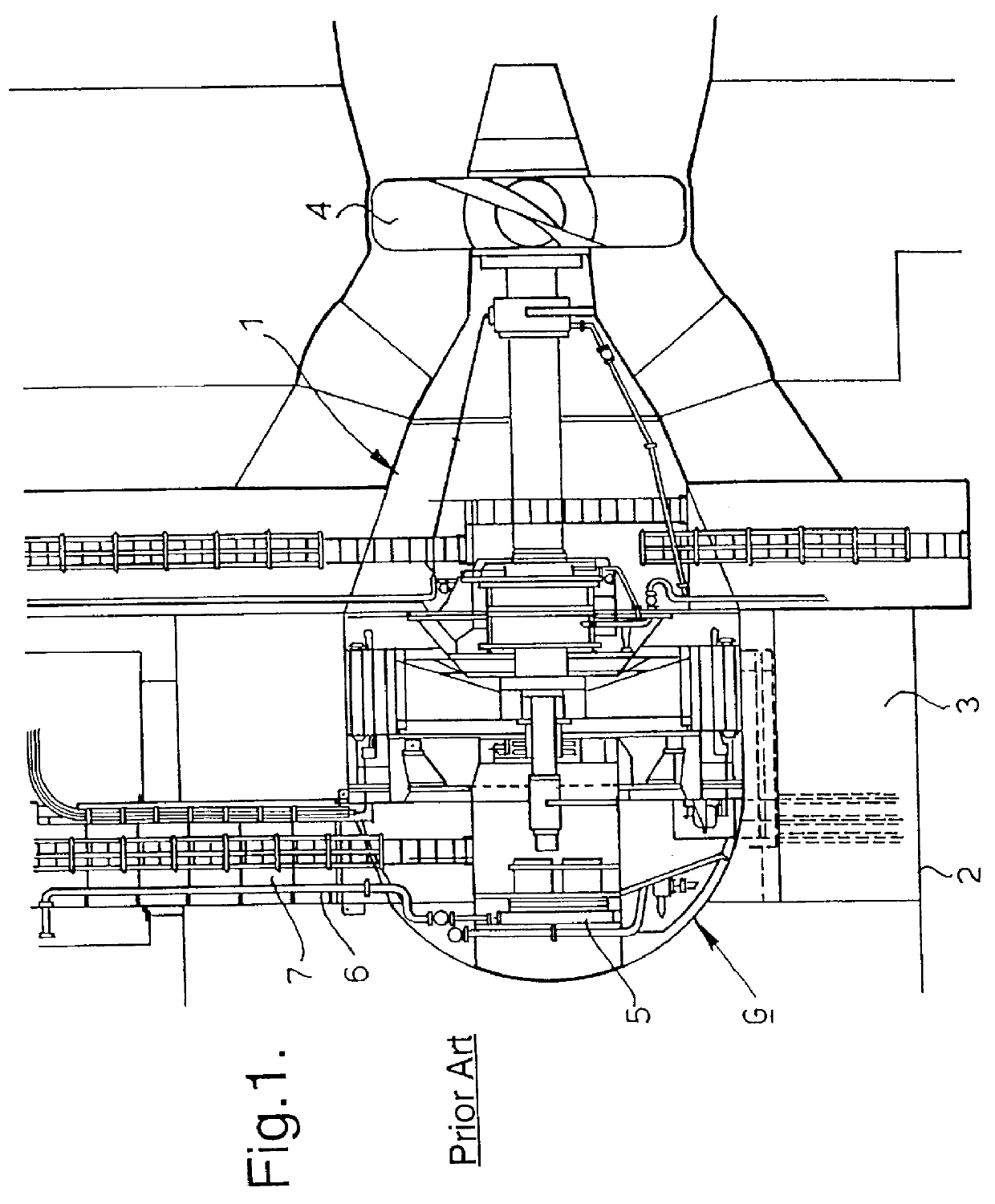
In FIG. 1 which illustrates a schematical section through a bulb type hydro generator G, the bulb or the generator housing itself is designated by reference numeral 1, said generator housing 1 constituting the main member of a hydro generator which is located in a turbine pipe 2 wherethrough river water 3 or similar flows therealong and towards the turbine 4 provided downstreams in relation to said generator housing 1.

The hydro generator G illustrated in FIG. 1, comprises a conventional technique for cooling said hydro generator, said generator comprising water / air heat exchanges 5 located down in the bulb, the water being supplied from outside via pipes 6 through the access shaft 7 of the generator. The cooling water itself is taken from the river water, which often requires filters due to the quality of the river water, which in turn makes the installation of a river generator more expensive and complicated.

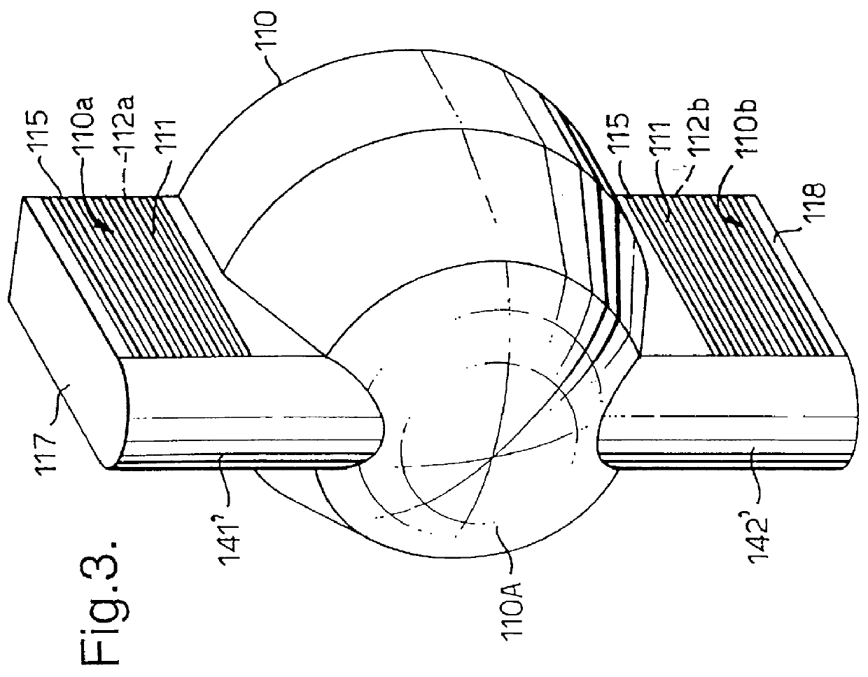
In FIG. 2 there is perspectively illustrated a view of the front nose port...


PUM


Abstract

PCT No. PCT/NO96/00213 Sec. 371 Date Jun. 8, 1998 Sec. 102(e) Date Jun. 8, 1998 PCT Filed Aug. 29, 1996 PCT Pub. No. WO97/09771 PCT Pub. Date Mar. 13, 1997The present invention relates to an arrangement in a bulb generator (G), comprising a generator housing (1, 10, 110, 210, 310, 410) arranged in a water flow for letting turbine water flow there along and towards the turbine (4), which arrangement comprises means for removing surplus heat generated during operation of the generator, which mean comprise elements which are assembled as flow channels for coolant and/or heated generator air for indirect or direct cooling of the generator air, and for the purpose of providing a cooling system which to a large degree is independent of the quality of the river water or turbine water, and which also comprises elements which are non-costly as regards manufacturing and assembly, it is according to the present invention suggested that said means (111; 411) comprise, as known per se, extruded elements, especially elements which either comprise channels or by assembly define channels (112; 412) for circulating coolant, especially circulating air, or any other appropriate coolant, and that an outer surface of the extruded elements is exposed to bypassing turbine water.

Description

The present invention relates to an improved arrangement in a bulb generator, comprising a generator housing arranged in a water flow which flows therealong and towards the turbine, which arrangement comprises means for removing surplus heat generated during operation of the generator, which means comprise elements which are assembled as flow channels for coolant and / or heated generator air for indirect or direct cooling of the generator airPRIOR ARTA known technique for cooling bulb generators comprises water / air-heat exchangers located in the generator housing or bulb, the water being supplied from outside via pipes down the access shaft of the generator. Such an arrangement is often hampered with problems, inter alia because filters are required due to the quality of the river water.It has also been suggested to use the bulb wall as a heat exchanger in order to avoid said problems. In such an arrangement the bulb wall is made double in the conical part of the nose portion, such t...

Claims


Application Information

Patent Timeline
Patent Type & Authority Patents(United States)
IPC IPC(8): F03B13/00F03B11/02F03B13/10F03B11/00H02K9/00H02K9/18
CPCF03B11/02F03B13/105H02K5/20H02K9/005F05B2260/20F05B2260/221Y02E10/22Y02E10/226Y02E60/17Y10S60/912Y02E10/20Y02E60/16H02K9/00H02K5/203H02K5/207
Inventor GEVELT, BJ.O SLASHED.RNOFTEDAL, K.ANG.RE OLAF
Owner ALSTOM TECH LTD
Why Eureka
Try Eureka