Self positioning fixation system and method of using the same

a fixation system and self-positioning technology, applied in the direction of lifting devices, artificial islands, constructions, etc., can solve the problem that the stopper may not fully engage the tooth space, and achieve the effect of preserving the integrity of the mating surface surfa

Inactive Publication Date: 2000-02-29
OFFSHORE TECH DEVMENT PTE +1
View PDF15 Cites 22 Cited by
  • Summary
  • Abstract
  • Description
  • Claims
  • Application Information

AI Technical Summary

Benefits of technology

It is a further object of the present invention to provide a new fixation system for self elevating platform which will successfully transfer the load from the jack foundation to the leg assembly or vice versa even when the leg assembly has angular misalignment with the rack chock in any direction.
It is a further object of the present invention to provide a new fixation system for self elevating platform which automatically engages and disengages with the leg rack while preserving surface integrity of the mating surfaces.

Problems solved by technology

Where the movement of stoppers is in a direction substantially perpendicular to the leg rack, the stoppers may not engage fully into the tooth space in all relative positions of the hull with respect to the leg.

Method used


Image

  • Self positioning fixation system and method of using the same
  • Self positioning fixation system and method of using the same
  • Self positioning fixation system and method of using the same

Examples


Embodiment Construction

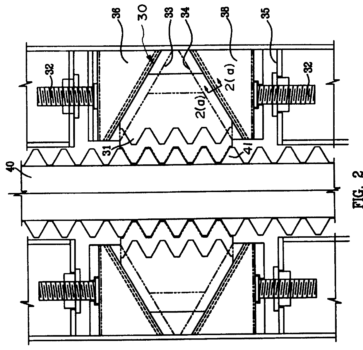
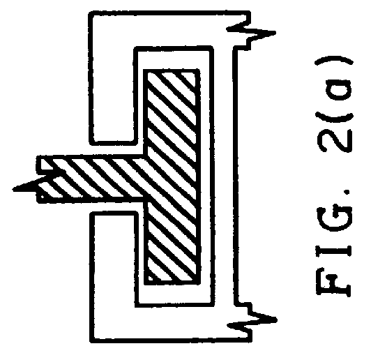
A method and apparatus for positioning a fixation device automatically and arresting the relative movement between the supporting legs and hull of self elevating platform is described. In the following description, numerous specific details are set forth such as rack, pin and program steps, etc. in order to provide a thorough understanding of the present invention. It will be obvious to one skilled in the art that the present invention may be practiced without these specific details. In other instances, well-known parts such as those involved with the rack and pinion jacking system are not shown in order not to obscure the present invention.

Notation and Nomenclature

The detailed description with respect to the steps of positioning automatically the rack to the leg rack are presented partially in terms of algorithm and symbolic representation upon operation on data bits within the computer memory. These algorithmic descriptions and representations are the means used by those skilled i...


PUM


Abstract

The present invention has at least one rack chock which is supported pivotally and tiltably at one end by a pin and cross head assembly located at a position between at least one leg rack and the hull of the platform. The other end of the rack chock is connected to the jack foundation with an actuator assembly. The pin and cross head assembly is disposed slidably within a guide for permitting the teeth of the rack chock to engage the leg rack teeth without visual monitoring and manual control. The actuator assembly connected to the other end of the rack chock controls the swinging movement of the rack chock and its engagement and disengagement with the leg rack. A pair of jacks urges upper and lower wedges with tiltable surfaces converging onto the rack chord's upper and lower surfaces, thus obtaining a optimal surface to arrest the relative movement between the rack chock and the leg rack. As such, load from the jack foundation is transferred to the legs, overturning moments on the legs to the jack foundation. Stress to the mating surfaces of the present invention and the leg rack is minimized as the engagement of the present invention takes place under load from the inertia load of the rack chock due to the pivoting action with minimum forcing action from the actuator assembly.

Description

The present invention relates to a fixation system for self elevating platform or jackup rig. In particular, the present invention pertains to a system for automatically engaging the fixation device to arrest the relative movement between the supporting legs and hull of self elevating platform while preserving surface integrity of the mating surfaces.Various prior art fixation systems are employed to arrest the relative motions and transfer the overturning moments and loads between the hull and legs of a jackup rig.A jackup rig as used herein means any working platform for drilling, work over, production, crane work, compressor station, diving support or other offshore purpose in an elevated position above the water, and being supported on jackable legs to the ocean floor or other water bottom, with the inherent capability of relocating from one site to another by lowering to a floating position, and after being moved to a new established location, raising again to an elevated posit...

Claims


Application Information

Patent Timeline
Patent Type & Authority Patents(United States)
IPC IPC(8): E02B17/00E02B17/06
CPCE02B17/06
Inventor FOO, KOK SENGREGE, GOVIND RAGHUNATH
Owner OFFSHORE TECH DEVMENT PTE
Why Eureka
Try Eureka