Method and apparatus for screen printing on a hard substrate

a technology of hard substrate and screen printing, applied in the direction of printing, other printing apparatus, rotary presses, etc., can solve the problem of insufficient screen printing to the edge of the substrate, and achieve the effect of reducing processing time, and reducing ink carrying capacity

Inactive Publication Date: 2000-03-07
PILKINGTON AUTOMOTIVE UK
View PDF20 Cites 28 Cited by
  • Summary
  • Abstract
  • Description
  • Claims
  • Application Information

AI Technical Summary

Benefits of technology

The method according to the invention enables substrates to be printed right up to but not on to their edges using standard printing apparats and without increased processing times. Ink is only transferred from ink permeable areas which contact the substrate sure. As the part of the screen which contacts the region of the substrate adjacent the edge has only a reduced ink carrying capacity, only a limited quantity of ink is transferred on to that region: this quantity is carefully calculated so that although there is sufficient to form a continuous coating, there is insufficient to spread on to the edge of the substrate.
In addition to enabling printing specifically up to the edge of a substrate, the method according to the invention also allows for a degree of mis-registration of the screen and the substrate. Having a reduced ink carrying capacity part in the screen means that there can be an increase in the tolerance with which the screen is located over the substrate and to variations in the size of the substrate. As long as the edge up to which the printing is to take place lies somewhere under a reduced ink carrying capacity part, printing will always be up to but not beyond the edge. Again, this is achieved by appropriately calculating the ink carrying capacity across the reduced ink carrying capacity part. Consequently, mis-registration distances up to the width of a reduced ink carrying capacity part are possible whilst still providing a print up to the edge. This proves a particularly useful feature when printing around holes in the substrate, for example, when the substrate is a vehicle side window, holes are often provided to take body fastenings and these holes are often surrounded by a printed area which has to extend right up to the edge of the hole.

Problems solved by technology

As the part of the screen which contacts the region of the substrate adjacent the edge has only a reduced ink carrying capacity, only a limited quantity of ink is transferred on to that region: this quantity is carefully calculated so that although there is sufficient to form a continuous coating, there is insufficient to spread on to the edge of the substrate.

Method used


Image

  • Method and apparatus for screen printing on a hard substrate
  • Method and apparatus for screen printing on a hard substrate
  • Method and apparatus for screen printing on a hard substrate

Examples


Embodiment Construction

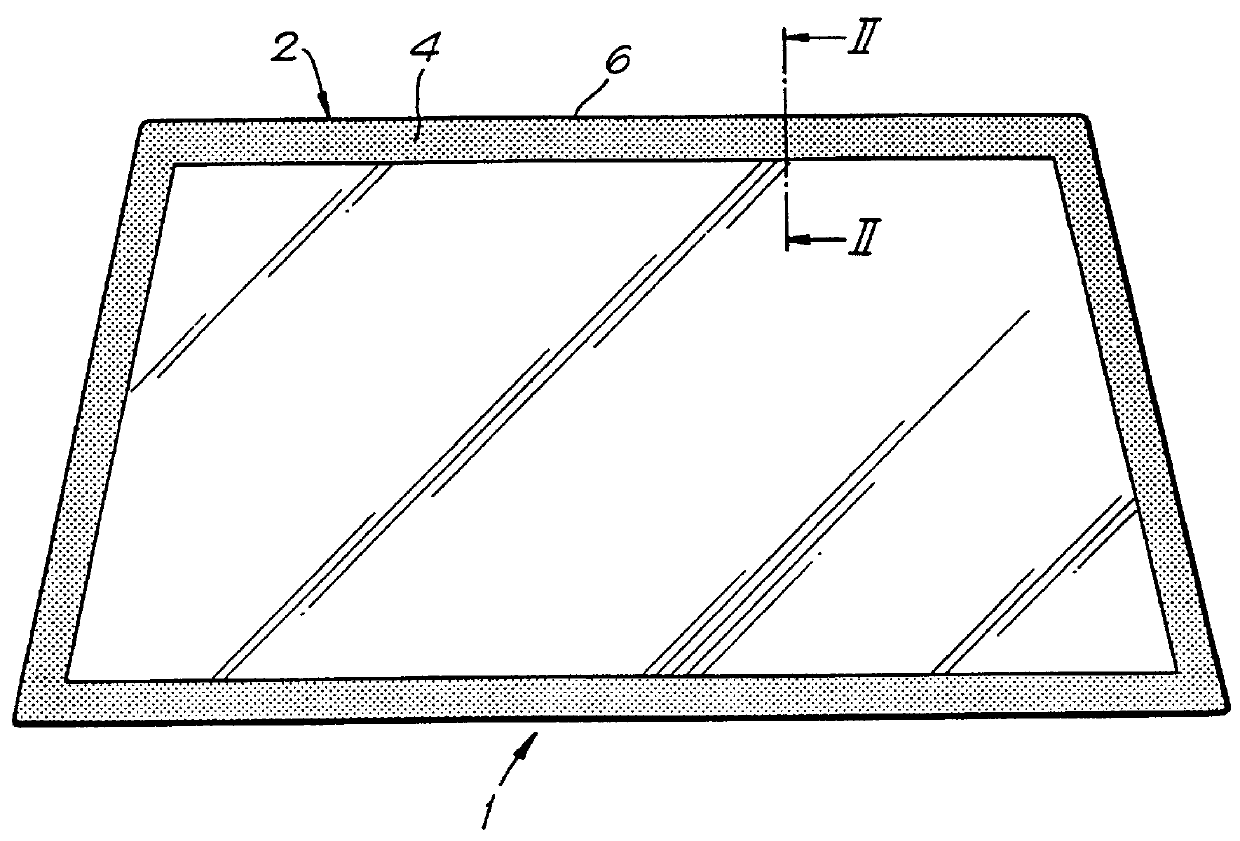
FIG. 1 illustrates a vehicle front window indicated generally at 1 which has been printed using a method according to the invention with a black obscuration band 4 around its peripheral margin 2. The band 4 is 40 mm wide, extends completely across the margin 2 and right up to but not on to the peripheral edge 6 of the window 1.

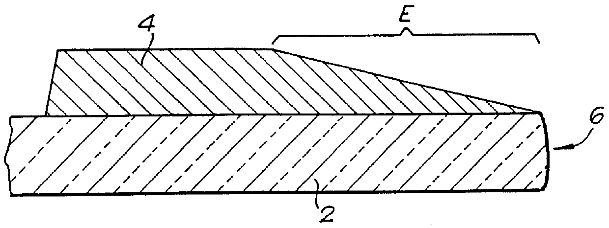
FIG. 2 shows the peripheral margin 2 of the window 1 in cross-section. The obscuration band 4 varies in thickness in the transverse direction. The band 4 is of generally uniform thickness further away from the edge 6 but over the region E adjacent the edge 6 the band 4 becomes gradually thinner, deceasing in thickness towards the edge 6. This edge region E is only of the order of 3-5 mm wide (largely exaggerated for clarity in the figures) so any difference in the colour density as a result of the reduced thickness at the band edge is imperceptible to the naked eye. The variation in thickness may be achieved by altering the structure of a conventional printing...


PUM


Abstract

PCT No. PCT/GB96/01215 Sec. 371 Date Jan. 27, 1998 Sec. 102(e) Date Jan. 27, 1998 PCT Filed May 21, 1996 PCT Pub. No. WO96/40525 PCT Pub. Date Dec. 19, 1996A method of screen printing on to a hard non-absorbent substrate (1) involves using a screen (10) which has an ink permeable area (B) whose pattern corresponds to whatever is to be printed. The area B is divided into two parts (X and Y). Part X is of normal, maximum, ink carrying capacity and part Y is of reduced ink carrying capacity. The ink carrying capacity of the reduced ink carrying capacity part Yis determined by the extent to which it is coated with ink/impenetrable emulsion (20), the size of the pores (18) in the screen (10) and the type of ink used. The ink carrying capacity of the part Y reduces with distance away from part X. The emulsion coating (20) may be in the form of dots (200), with the dots (200) increasing in diameter with distance away from part X. During printing, the reduced ink carrying capacity part Y is located over the edge region (E) of the substrate (1), and the substrate is printed up to but not on to its edge (6).

Description

The invention relates to printing and in particular to a method of screen printing on to a hard non-absorbent substrate such as glass. The invention also relates to a hard non-absorbent screen printed substrate and to a screen for use in printing on to such a substrate.Vehicle windows are commonly printed around their peripheral margins with so-called obscuration bands. These are opaque, usually black, and may cover the rough vehicle body parts, wires etc which underlie the peripheral margin of the window, or may help to protect the adhesive bonding the window to the vehicle body from UV degradation.The printing on to a vehicle window is normally done using a silk screen process. The screens are prepared to be selectively permeable to ink. Some areas of the screen are blocked out and other areas are left open. The open, ink permeable areas correspond to the patterns, for example, the obscuration band, which are to be printed on the glass.The preparation of a printing screen involves...

Claims


Application Information

Patent Timeline
Patent Type & Authority Patents(United States)
IPC IPC(8): B41C1/14B41M1/12B41F17/14B41F15/34B41N1/24
CPCB41C1/14B41M1/12B41M1/34
Inventor COLLINS, TERENCE WILLIAM
Owner PILKINGTON AUTOMOTIVE UK
Why Eureka
Try Eureka