System for depressurizing, filtering, and noise suppression of high pressure pneumatic vessels

a high-pressure pneumatic and filtering technology, applied in the field of system for venting and depressurizing high-pressure pneumatic vessels, can solve the problems of pneumatic transfer context, relative old age, and the inability to work in high-pressure environments, and achieve the effects of safe, reliable, and cost-effectiv

Inactive Publication Date: 2000-03-14
RIBARDI HARRIS J +1
View PDF20 Cites 45 Cited by
  • Summary
  • Abstract
  • Description
  • Claims
  • Application Information

AI Technical Summary

Benefits of technology

Unlike the prior art, the present invention provides a system for venting and depressurizing high pressure pneumatic vessels with filtration and noise suppression of the vented air, in an efficient, safe, reliable, and cost-effective manner. Further, unlike other systems, the present system is configured to be relatively self-maintaining, and is configured to be installed at an installation for an extended period of time, requiring only nominal operational input from personnel.

Problems solved by technology

While filter bags remove most of the particulates form the vented air, the technology is relatively old and this means of filtration is not as efficient as other filter media employed in other areas.
Further, filter bags do not greatly dampen the noise created during the venting process, which can be deafening.
Howell is a low pressure system, and it is believed would not work in a high pressure, pneumatic transfer context.
The deficiencies in the prior art and methods for venting process air and depressurizing high pressure vessels lie in the need for continuous venting and dust removal and silencing the noise associated with venting high pressure vessels.

Method used


Image

  • System for depressurizing, filtering, and noise suppression of high pressure pneumatic vessels
  • System for depressurizing, filtering, and noise suppression of high pressure pneumatic vessels
  • System for depressurizing, filtering, and noise suppression of high pressure pneumatic vessels

Examples


Embodiment Construction

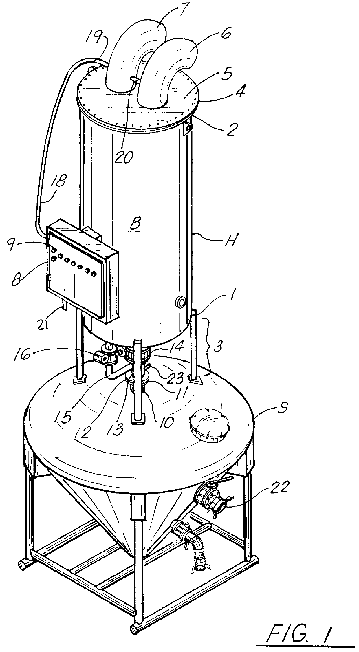
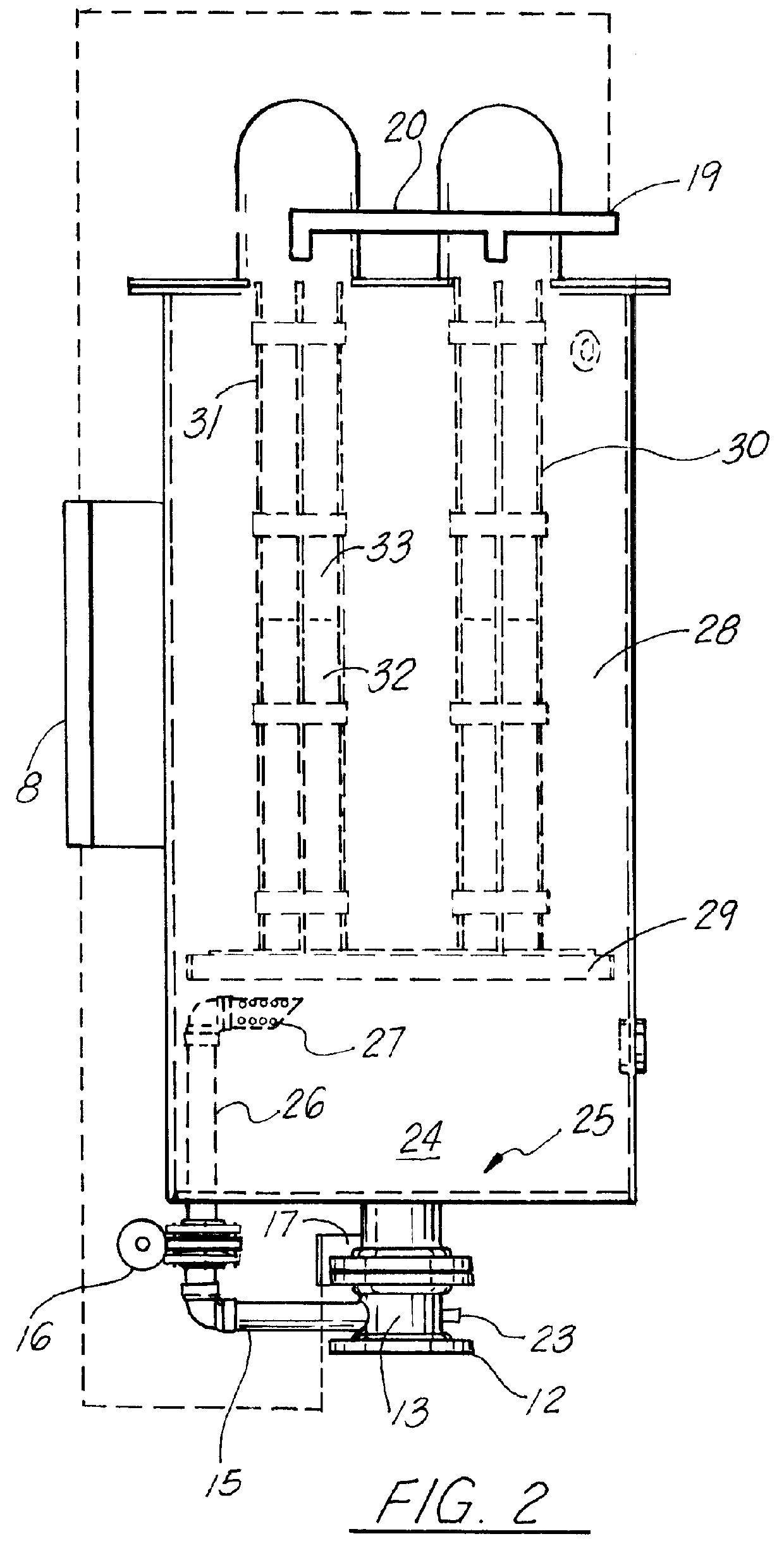
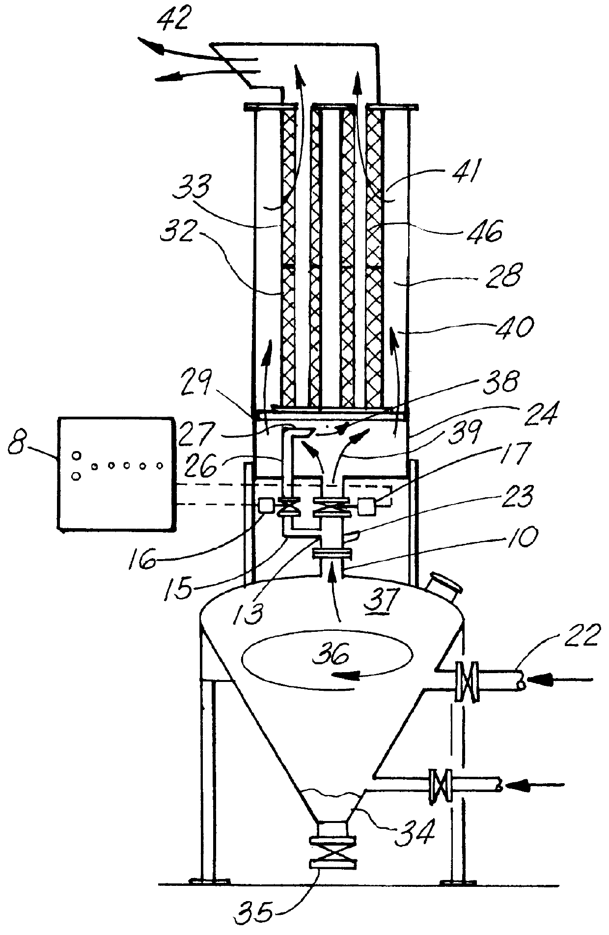
Referring to FIGS. 1 and 2, the preferred embodiment of the present invention comprises a housing H configured to engage a high pressure tank, such as surge tank S, the housing H having a body B having first 1 and second 2 ends, the first end 1 having legs 3, the second end having a flange 4 configured to engage lid 5, which includes first 6 and second 7 vents for venting filtered air therefrom.

Mounted along the side of the housing is a control panel 8 having controls 9 to control the system, the detailed operation of which will be more fully disclosed infra.

Situated at the top of the surge tank S is a vent 10 having a flange 11 thereupon, which communicates with the housing H of the present invention via mounting flange 12 formed at the terminus of main vent tube 13 which leads to intake chamber 24 via main intake aperture 25, and is regulated by main actuator 17 at flange 14. The actuator currently utilized in the working prototype is a TK130DA model by Trial Controls, Inc. of Cin...


PUM

PropertyMeasurementUnit
diameteraaaaaaaaaa
diameteraaaaaaaaaa
outer diameteraaaaaaaaaa

Abstract

A pressure vessel venting, dust collecting, and noise silencing system for continuous venting of dry process air during the filling and depressurization of pressure vessels configured to contain, for example, barite or the like, by filtering of vented air through a filter media, with the air discharge being controlled by a pressure sensor actuating a depressurizing regulator valve, located between the vessel and the filter. The present system contemplated a filter which may be cleaned by reverse pulse pressurization or backwash, thereby providing low maintenance filtration while preventing particle emissions into the atmosphere. The present system utilizes a high capacity, stacked filtration medium, which provides a greater filtration, with a surface contact area far in excess of the present systems on the market, which primarily rely upon bag house filtration. The present system thereby provides a low maintenance, efficient, and relatively cost effective system of controlled, filtered, and silenced venting on a process which would otherwise emit particulates into the air, while generating a significant amount of noise in the process.

Description

This invention relates to systems providing filtered, noise dampened venting of high pressure vessels, and in particular to a pressure vessel venting, dust collecting, and noise silencing system for continuous venting of dry process air during the filling and depressurization of pressure vessels containing dry particulate fluid substances including, for example, lime, barite or the like, by filtering of vented air through a filter media, with the air discharge being controlled by a pressure sensor actuating a depressurizing regulator valve, located between the vessel and the filter. The present system contemplates a filter array which may be cleaned by reverse pulse pressurization or backwash, thereby providing low maintenance filtration while preventing particle emissions into the atmosphere.The present system utilizes a high capacity, stacked filtration medium, which provides a greater filtration, with a surface contact area far in excess of the present systems on the market, whic...

Claims


Application Information

Patent Timeline
Patent Type & Authority Patents(United States)
IPC IPC(8): B01D46/04B01D46/00B01D46/24B01D50/00
CPCB01D46/0068B01D46/2411B01D46/4236B01D50/002B01D46/71B01D50/20
Inventor RIBARDI, HARRIS J.OSBURN, LARRY JOE
Owner RIBARDI HARRIS J
Why Eureka
Try Eureka