Rotational molding apparatus and method using infrared thermometry

a technology of infrared thermometry and molding apparatus, which is applied in the direction of applications, manufacturing tools, instruments, etc., can solve the problems of large amount of wasted material, difficult to know when the powder has melted, and difficult to know how long the mold should remain in the oven

Inactive Publication Date: 2000-03-14
FERRY IND
View PDF18 Cites 16 Cited by
  • Summary
  • Abstract
  • Description
  • Claims
  • Application Information

AI Technical Summary

Benefits of technology

It is a further object of this invention to provide a rotational molding apparatus that can continuously measure the temperature of the mold.

Problems solved by technology

The rotational molding technique has been used commercially for about 37 years but there are a number of practical problems.
Firstly, it is very difficult to know when the powder has melted.
This is usually established by trial and error and results in a considerable amount of wasted material.
Also, even when the powder has melted, it is difficult to know how long the mold should remain in the oven to obtain the optimum properties from the molded article.
Rotational molding to date has no means of attaining closed loop control due to the difficulties of gathering data continuously during the production.
However, the above system is limited in that the operation of the transmitting is restricted by the temperature of the oven which prevents the sensor from being used continuously in a production environment.
Furthermore, the positioning of the sensor within the rotating mold and the positioning of the microprocessor on the rotating arm makes this system complex and introduces failure modes due to this movement.

Method used


Image

  • Rotational molding apparatus and method using infrared thermometry
  • Rotational molding apparatus and method using infrared thermometry
  • Rotational molding apparatus and method using infrared thermometry

Examples


Embodiment Construction

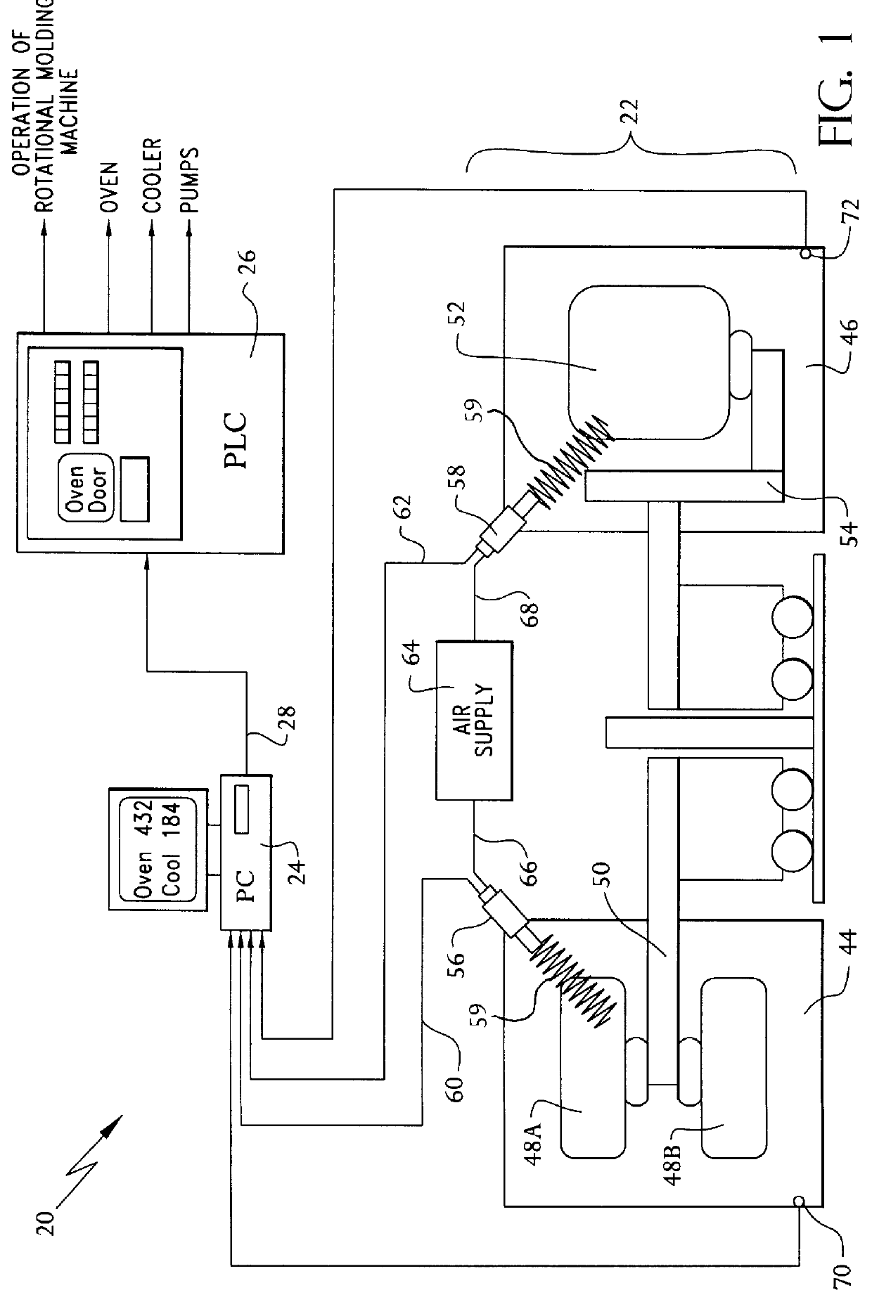
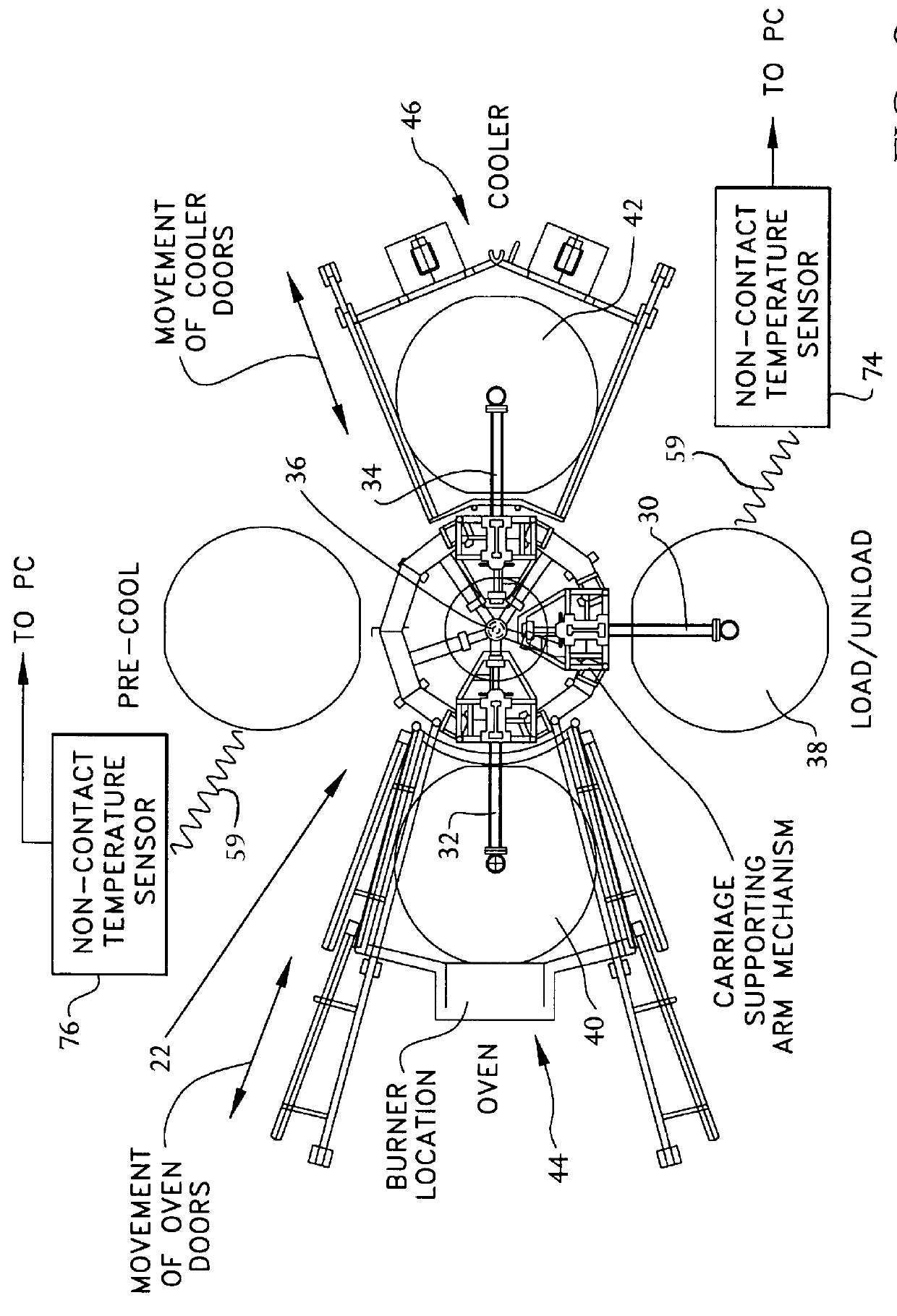
Referring now in greater detail to the various figures of the drawing wherein like reference characters refer to like parts, a rotational molding apparatus (hereinafter "RMA") constructed in accordance with the present invention is shown generally at 20 in FIG. 1.

The RMA 20 comprises a rotating molding machine 22 (e.g., a Ferry 280 Carousel Style Rotational Molding Machine), a conventional personal computer (PC) 24 having 4-20 mA circuit (not shown) that is connected to an A / D converter (also not shown) installed in the PC 24, and a conventional programmable logic controller (PLC) 26. In general, the PLC 26 controls the entire RMA 20 operation based on, among other things, inputs 28 from the PC 24. It is within the broadest scope of this invention that the inputs 28 can be directly fed to the PLC 26 from the PC 24 (through an electronic coupling), or alternatively, an operator (not shown) can manually feed these inputs 28 into the PLC 26.

Although any type of rotating molding machine...


PUM

PropertyMeasurementUnit
temperatureaaaaaaaaaa
wavelengthsaaaaaaaaaa

Abstract

A rotational molding apparatus that utilizes stationary temperature sensors, e.g., infra-red thermometry (IRT) sensors, for continuously monitoring the temperature of the molds during rotation.

Description

SPECIFICATION1. Field of the InventionThis invention relates generally to molding apparatus, more particularly, to rotational molding processes.2. Background of the InventionRotational molding is a processing method for producing hollow articles made of synthetic plastics material. The process involves the steps of: (1) placing a measured amount of powdered or liquid plastic material in a hollow metal, glass fiber reinforced or ceramic mold; (2) rotating the mold about two perpendicular axes to distribute the material around the inner surface; (3) placing the rotating mold in an oven to heat the material and cause it to adhere to the inner surface of the mold; (4) cooling the mold using air, water or a combination of both to solidify the plastic to form a hollow part; and (5) removing the part from the mold. U.S. Pat. Nos. 4,183,883 (Blair); 4,241,005 (Rothschild et al.); 4,331,626 (Colby); 4,755,333 (Gray); 4,970,045 (Steinberg et al.); 5,316,701 (Payne); 5,503,780 (Payne) and 5,70...

Claims


Application Information

Patent Timeline
Patent Type & Authority Patents(United States)
IPC IPC(8): B29C33/00B29C33/36B29C41/04B29C41/34B29C41/46B29C41/52B29C41/06
CPCB29C33/36B29C41/04B29C41/06B29C41/46B29C41/52B29C2037/906
Inventor NUGENT, PAUL J.
Owner FERRY IND
Why Eureka
Try Eureka