

Thermal printing method and thermal printer
- Summary
- Abstract
- Description
- Claims
- Application Information
AI Technical Summary
Benefits of technology
Problems solved by technology
Method used
Image

Examples
Embodiment Construction
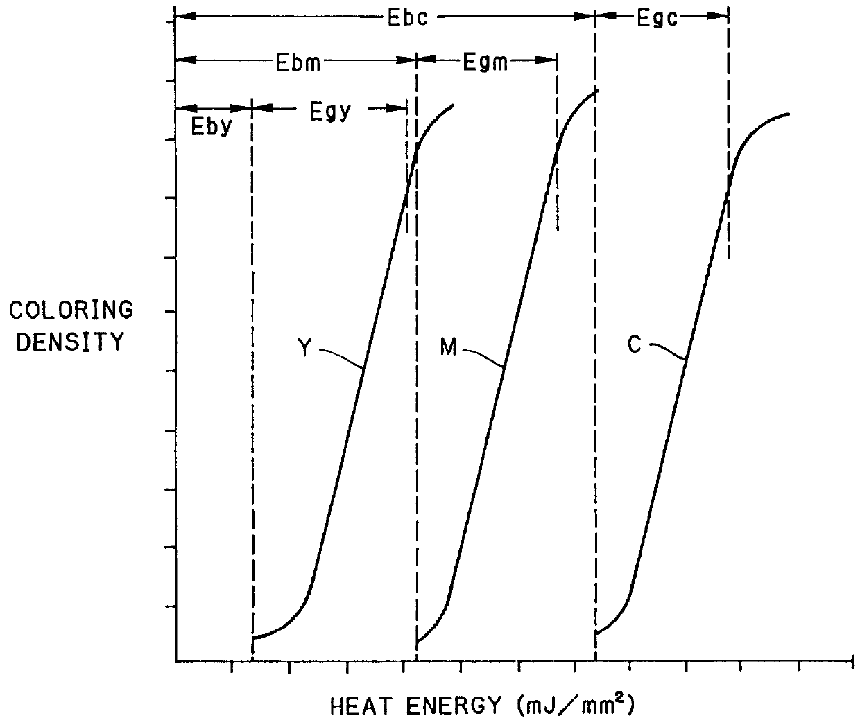
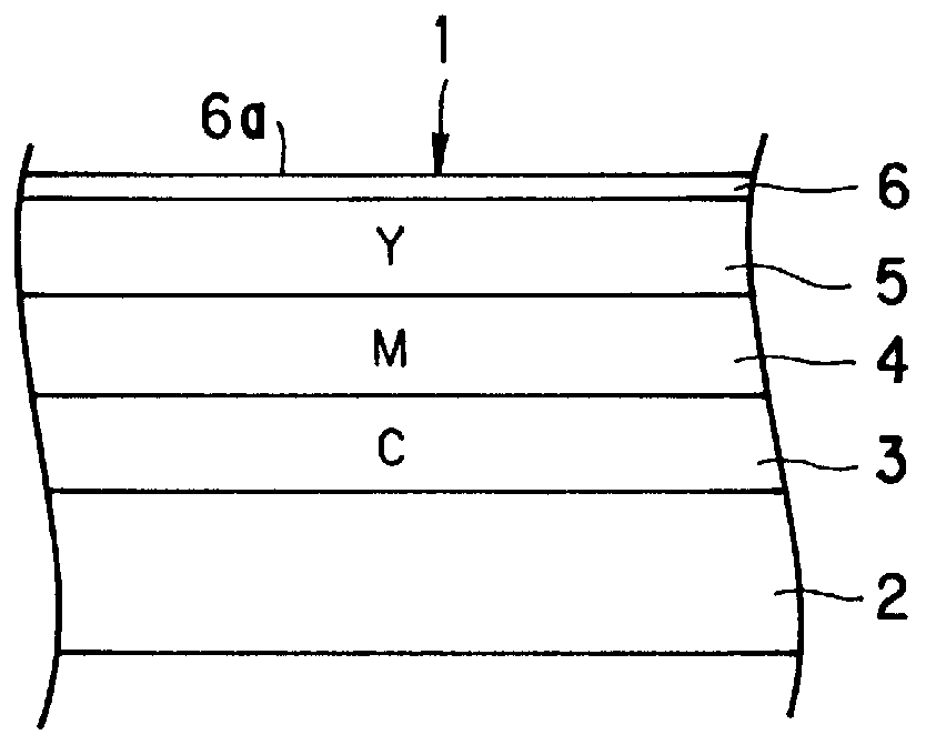
In FIG. 1 illustrating a layered structure of a color thermosensitive recording sheet 1, the recording sheet 1 includes a support 2, a cyan coloring layer 3, a magenta coloring layer 4, a yellow coloring layer 5 and a protective layer 6 disposed in the order listed. The magenta coloring layer 4 has photochemical fixability responsive to ultraviolet rays of a wavelength range of nearly 365 nm. The yellow coloring layer 5 has photochemical fixability responsive to near ultraviolet rays of a wavelength range of nearly 420 nm. Recording operation is effected in the order from an obverse surface or recording surface toward the support 2, namely yellow, magenta and cyan. It is also possible to use an alternative recording sheet including the support 2, the cyan coloring layer 3, the yellow coloring layer 5, and the magenta coloring layer 4 disposed in the order listed. With this recording sheet, recording operation is effected in the order magenta, yellow and cyan. There are intermediate ...
PUM
| Property | Measurement | Unit |
|---|---|---|
| Temperature | aaaaa | aaaaa |
| Density | aaaaa | aaaaa |
| Sensitivity | aaaaa | aaaaa |
Abstract
Description
Claims
Application Information