Camera capable of video and film shooting having optical viewfinder

a technology of optical viewfinder and camera, which is applied in the field of cameras, can solve the problems of not being able to free-place a distance measurement device, video cameras are not capable of silver-halide shooting, and cameras are not able to video shoo

Inactive Publication Date: 2000-03-21
MINOLTA CO LTD
View PDF14 Cites 48 Cited by
  • Summary
  • Abstract
  • Description
  • Claims
  • Application Information

AI Technical Summary

Problems solved by technology

In general, video cameras are not capable of silver-halide shooting, and cameras based on silver-halide photography such as single-lens reflex cameras are not capable of video shooting.
A disadvantage of the above-mentioned camera is that it does not allow free placement of a distance measurement device.
However, in the arrangement shown in FIGS. 17A and 17B, where the half mirror HM is rotatable, it is impractical to place the distance measurement device above or below the mirror box, because the presence of a drive mechanism for rotating the half mirror HM imposes various restrictions on the placement of the distance measurement device and of an AF mirror (which is needed to direct light to the distance measurement device), and because the driving of the AF mirror in such a situation requires a complex mechanism.
Instead, if the distance measurement device is placed by the side of the mirror box, then the retraction of the AF mirror requires a complex mechanism and, in addition, it is difficult to secure space for the retracting motion of the AF mirror.
Another disadvantage of the above-mentioned camera is that it requires a relatively large mirror box.
This is because an unduly small half mirror HM may cause eclipse in the light flux directed to the silver-halide shooting system G, especially when a large-aperture interchangeable lens is used.
Since the half mirror HM is rotated to switch optical paths, a larger half mirror HM requires a larger mirror box, which inevitably makes the camera as a whole accordingly larger.
This, however, reduces the amount of light received by each of the systems G, V, and F to such an extent that they can no longer function properly.
Under this condition, the camera is excessively susceptible to hand shakes.
As described above, since types No. 1, 5, and 9 suffer from shortage of light, these types are not fit for practical applications.
Note that, although types Nos. 1, 5, and 9 allow concurrent use of the three systems, these types will not be dealt with further, since they suffer from shortage of light.
A construction in which light flux splitting and optical path switching are done within the taking lens has disadvantages that the taking lens needs to be larger and more complex (e.g. an image-sensing device needs to be fitted on the outer surface of the...

Method used


Image

  • Camera capable of video and film shooting having optical viewfinder
  • Camera capable of video and film shooting having optical viewfinder
  • Camera capable of video and film shooting having optical viewfinder

Examples


third embodiment

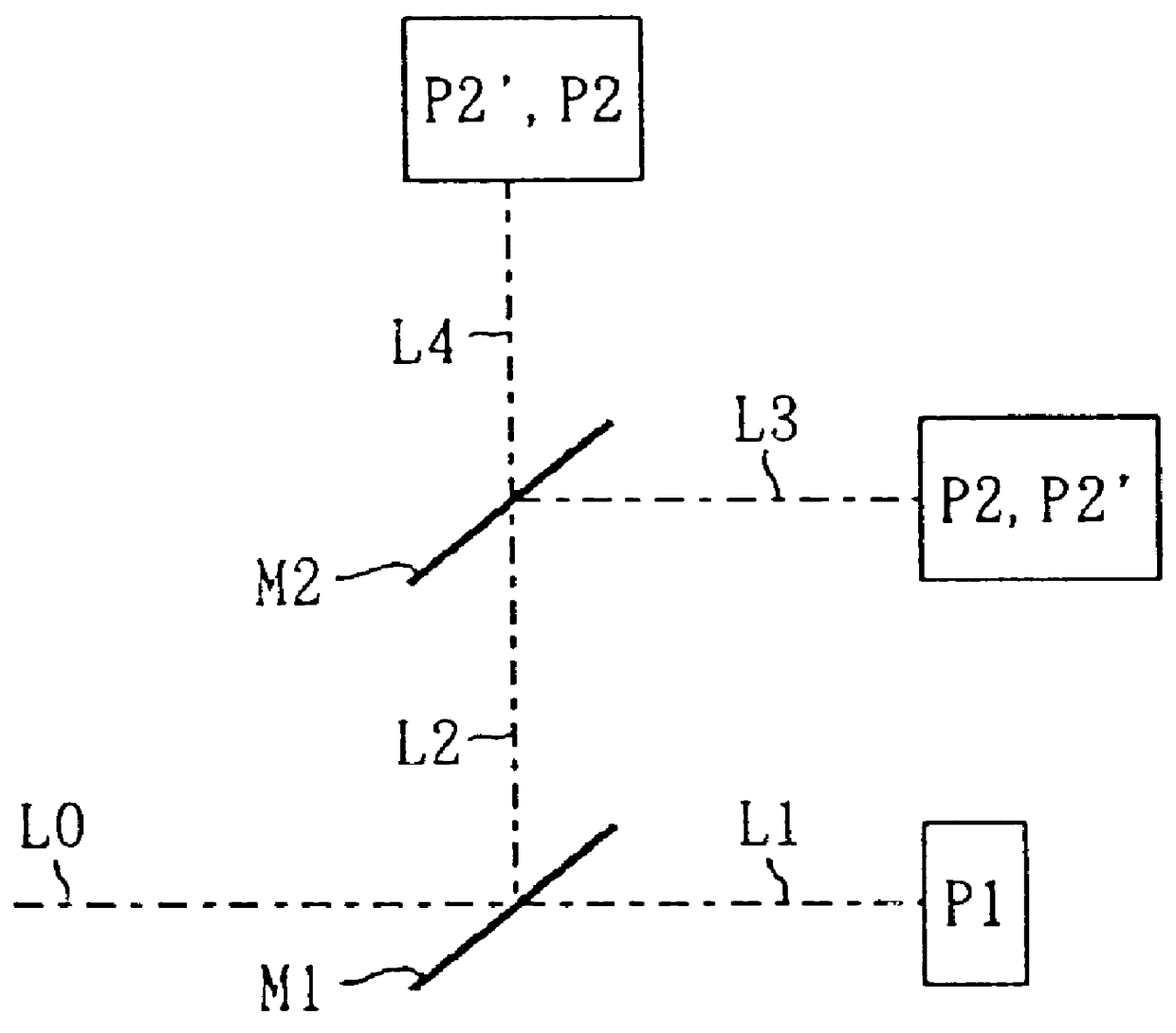
In this modified example, the pellicle mirror PM is so placed as to make an angle of about 45.degree. to the optical axis of the taking lens TL (represented by the dash-dot line indicating the light flux L0), and the rotatable mirror RM is placed in such a way that, when the optical path for the fourth light flux L4 is selected, the fourth light flux L4 travels obliquely toward the taking lens TL. Specifically, here, the rotatable mirror RM makes an angle of 55.degree. to the optical axis of the taking lens TL. As a result, between the taking lens TL and the optical viewfinder system F, light travels along a Z-shaped optical path, that is, a "Z optical system" is formed. Owing to this construction, the lens-back distance can be made still shorter than in the This not only helps simplify the lens design, but also makes it even easier to realize Advanced Photo System cameras that can be used in combination of interchangeable lenses for 135 cameras.

In FIGS. 13, 14, and 16, numeral 30 ...

fourth embodiment

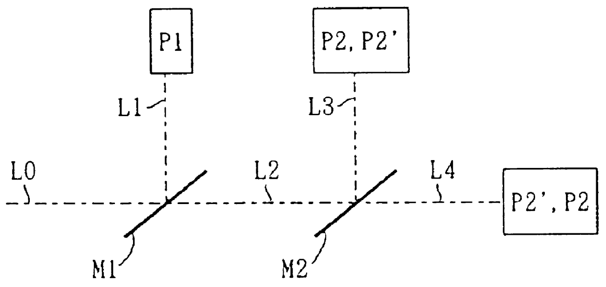
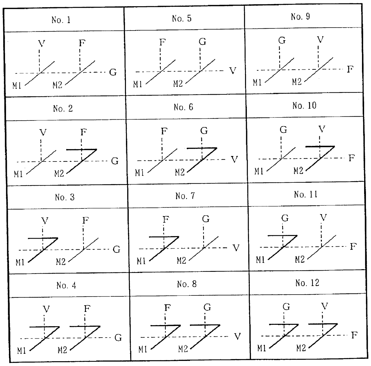
FIG. 7 schematically shows the internal construction of the camera of the This camera adopts construction type No. 7 (Table 1, FIG. 2) described earlier. In FIG. 7, each of the light flux L0 to L4 is represented by a paraxial ray.

first embodiment

A taking lens TL is housed in a lens barrel OP with such a lens-back distance that allows the light traveling from an object through the taking lens TL to be focused to form an image on the surface of a film 5. The lens barrel OP is formed as a single unit with a camera body BO, though it is also possible to design the lens barrel OP to be interchangeable as in the

Inside the camera body BO, a mirror box MB is provided for supporting a rotatable mirror RM, a pellicle mirror PM, an AF mirror SM, and other components. The rotatable mirror RM corresponds to the mirror M1 described earlier, and can be positioned either in position PA or in position PB by its rotation through a predetermined angle about a rotation axis P10. By switching the position of the rotatable mirror RM between positions PA and PB, the subsequent optical path of the light flux L0 having passed through the taking lens TL is switched between the optical path of a reflected light flux (a first light flux) L1 and that o...


PUM


Abstract

A camera is capable of both silver-halide shooting, through which object images are recorded on silver-halide film, and video shooting, although its distance measurement device is placed substantially in the same way and its mirror box has substantially the same size as in ordinary single-lens reflex cameras. In this camera, a pellicle mirror splits the light flux having passed through a taking lens into a first light flux and a second light flux, and a rotatable mirror switches the subsequent path of the second light flux between the optical path for a third light flux and the optical path for a fourth light flux. The pellicle mirror, through its light flux splitting function, directs the first light flux to a silver-halide shooting system, and directs the second light flux to the rotatable mirror. The rotatable mirror, through its optical path switching function, either directs the third light flux to an optical viewfinder system, or directs the fourth light flux to a video shooting system.

Description

1. Field of the InventionThe present invention relates to a camera, and more particularly to a camera that is capable of both silver-halide shooting (recording of object images as pictures on silver-halide film) and video shooting (recording of object images as electronically reproducible moving and still pictures).2. Description of the Prior ArtIn general, video cameras are not capable of silver-halide shooting, and cameras based on silver-halide photography such as single-lens reflex cameras are not capable of video shooting. However, Japanese Laid-open Patent Application No. H1-133038 proposes a camera that is capable of both silver-halide shooting and video shooting. This camera, as shown in FIGS. 17A and 17B, is provided with a half mirror HM that can rotate 90.degree. to change its position, so that the light flux having passed through the taking lens (not shown) is split by the half mirror HM into a reflected light flux and a transmitted light flux.When the half mirror HM is ...

Claims


Application Information

Patent Timeline
IPC IPC(8): G03B17/48H04N5/225
CPCG03B17/48H04N5/225H04N5/2251H04N23/55H04N23/00
Inventor HONDA, TSUTOMUMATSUMOTO, HIROYUKISUZUKI, TATSUYA
Owner MINOLTA CO LTD
Why Eureka
Try Eureka