Break-away processing tool for a waste processing machine

a technology of a processing tool and a waste processing machine, which is applied in the field of breakaway processing tools for waste processing machines, can solve problems such as damage to the rotor and/or the other processing tools of the rotor assembly

Inactive Publication Date: 2000-04-11
SMORACY
View PDF75 Cites 35 Cited by
  • Summary
  • Abstract
  • Description
  • Claims
  • Application Information

AI Technical Summary

Problems solved by technology

Although the above waste processing machine has worked well, it suffers from the disadvantage that a failure or breakage of the processing tool will allow a portion or broken piece of the processing tool to be loose and travel about the rotor, possibly resulting in damage of the rotor and / or the other processing tools of the rotor assembly.

Method used


Image

  • Break-away processing tool for a waste processing machine
  • Break-away processing tool for a waste processing machine
  • Break-away processing tool for a waste processing machine

Examples


Embodiment Construction

)

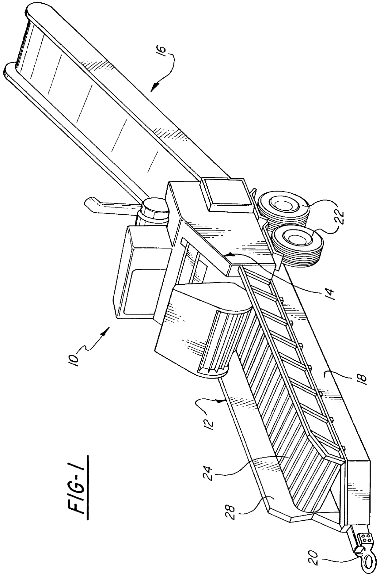
Referring now to the drawings and in particular to FIG. 1, one embodiment of a waste processing machine 10 for reducing waste product is shown. The waste processing machine 10 includes an infeed system 12, a waste reducing or cutting system 14, and a discharge system 16. Waste product enters the waste processing machine 10 through the infeed system 12 where it is directed to the cutting system 14. The cutting system 14 cuts or reduces the waste product and directs it to the discharge system 16 where the reduced waste product is expelled from the waste processing machine 10. The waste processing machine 10 may be supported on a trailer framework 18 having a tongue mount 20 provided at a front thereof and wheels 22 near a rear of the framework 18. It should be appreciated that, with this structure, the infeed system 12 and cutting system 14 can be transported together while the discharge system 16 can be transported separately therefrom.

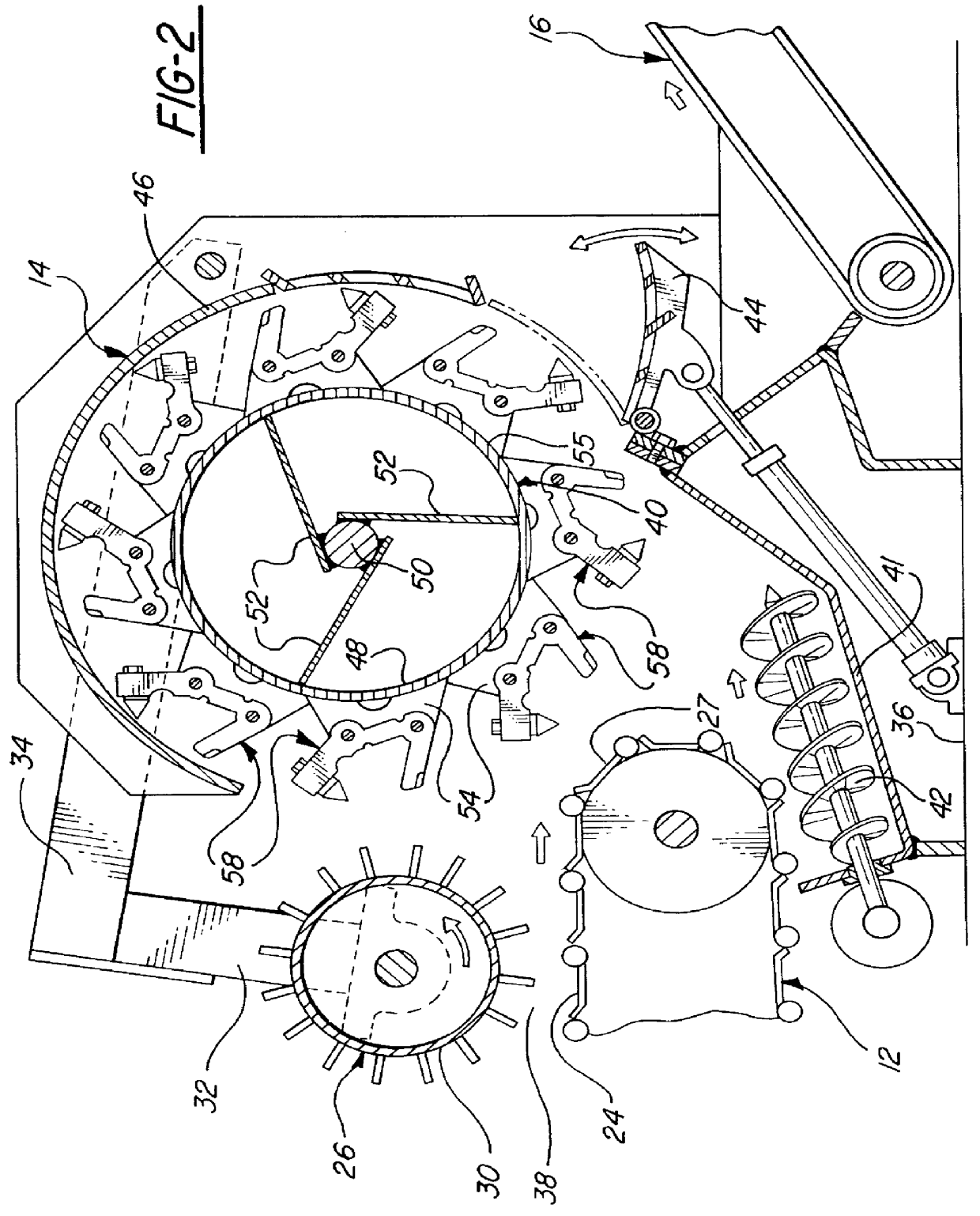
Referring to FIGS. 1 and 2, the infeed system 1...


PUM


Abstract

A break-away processing tool for a waste processing machine includes a tool holder, at least one fastener for attaching the tool holder to a rotor assembly of the waste processing machine and a structure for allowing breakage of the tool holder in a controlled manner such that broken pieces of the tool holder remains attached to the rotor assembly by the fastener.

Description

1. Field of the InventionThe present invention relates generally to waste processing machines and, more particularly, to a break-away processing tool for a waste processing machine.2. Description of the Related ArtIt is known to provide waste processing machines to reduce waste product. The waste processing machine typically includes a rotor assembly having a rotor and a plurality of processing tools attached to the rotor. The processing tool is provided with a cutting tool for reducing the waste product as the rotor rotates.An example of such a waste processing machine is disclosed in pending patent application, U.S. Ser. No. 08 / 637,233, filed Apr. 24, 1996, entitled "WASTE PROCESSING MACHINE", now U.S. Pat. No. 5,863,003 the disclosure of which is hereby incorporated by reference. In that application, the processing tool is generally C-shaped wherein a leading arm of the C-shape operates as a depth-limiting guide for the processing tool and a trailing arm of the C-shape includes a...

Claims


Application Information

Patent Timeline
IPC IPC(8): B02C18/14B02C18/06
CPCB02C18/145
Inventor SMITH, LEWARD N.
Owner SMORACY
Why Eureka
Try Eureka