Waste treatment autoclave to provide for steam - assisted drying

a technology of autoclave and steam, which is applied in the direction of transportation and packaging, disinfection, chemistry apparatus and processes, etc., can solve the problems of inability to provide efficient in situ drying, significant energy loss, and blockage of helical blades

Inactive Publication Date: 2010-06-03
ESTECH
View PDF28 Cites 23 Cited by
  • Summary
  • Abstract
  • Description
  • Claims
  • Application Information

AI Technical Summary

Benefits of technology

[0029]The present invention represents an improvement upon these systems via a system that heats contents with both contact and non-contact steam (maintaining separation of the contact steam from the non-contact steam) by distributing the non-contact steam for drying of contents via a system of blades that serve to both heat the contents and to mechanically agitate the contents, by maintaining the pressure of the steam in the blades so as to transfer heat released by the condensation of steam in the blades, and by an efficient system of regeneration of non-contact condensate that includes a mechanical vapor recompressor.
[0033]The doors provide for dual unions, to transfer steam and condensate from fixed locations to the rotating autoclave. A system of transferring steam from the autoclave door (removable) to the autoclave proper is also provided, using an annular groove on both sides of the door seal. This allows the door to be removed and returned without an alignment problem.

Problems solved by technology

One of the disadvantages of the arrangements of the prior art is that many autoclaves feature helical blades that resist material flow when the waste is loaded into the autoclave and when the treated waste mass is removed from the autoclave.
Helical blades also create blockages when stringy, fibrous material, such as clothing and rugs, is present.
Another disadvantage of prior systems is that they have not been able to provide efficient in situ drying, and to make efficient and effective use of waste steam for such a process.
Contact condensate is recirculated to the boiler, and a small (5%) bleed of steam from the TVR removes non-condensibles (with a significant loss of energy).
The current art eventually results in the detrimental release of the vapors to the contact steam condensate.
Further, experience shows that spent contact steam has substantial air content, with detrimental consequences to both heat transfer coefficient and to tube / boiler / plumbing material life.

Method used


Image

  • Waste treatment autoclave to provide for steam - assisted drying
  • Waste treatment autoclave to provide for steam - assisted drying
  • Waste treatment autoclave to provide for steam - assisted drying

Examples


Embodiment Construction

[0078]In accordance with the foregoing summary, the following provides a detailed description of the preferred embodiment, which is presently considered to be the best mode thereof.

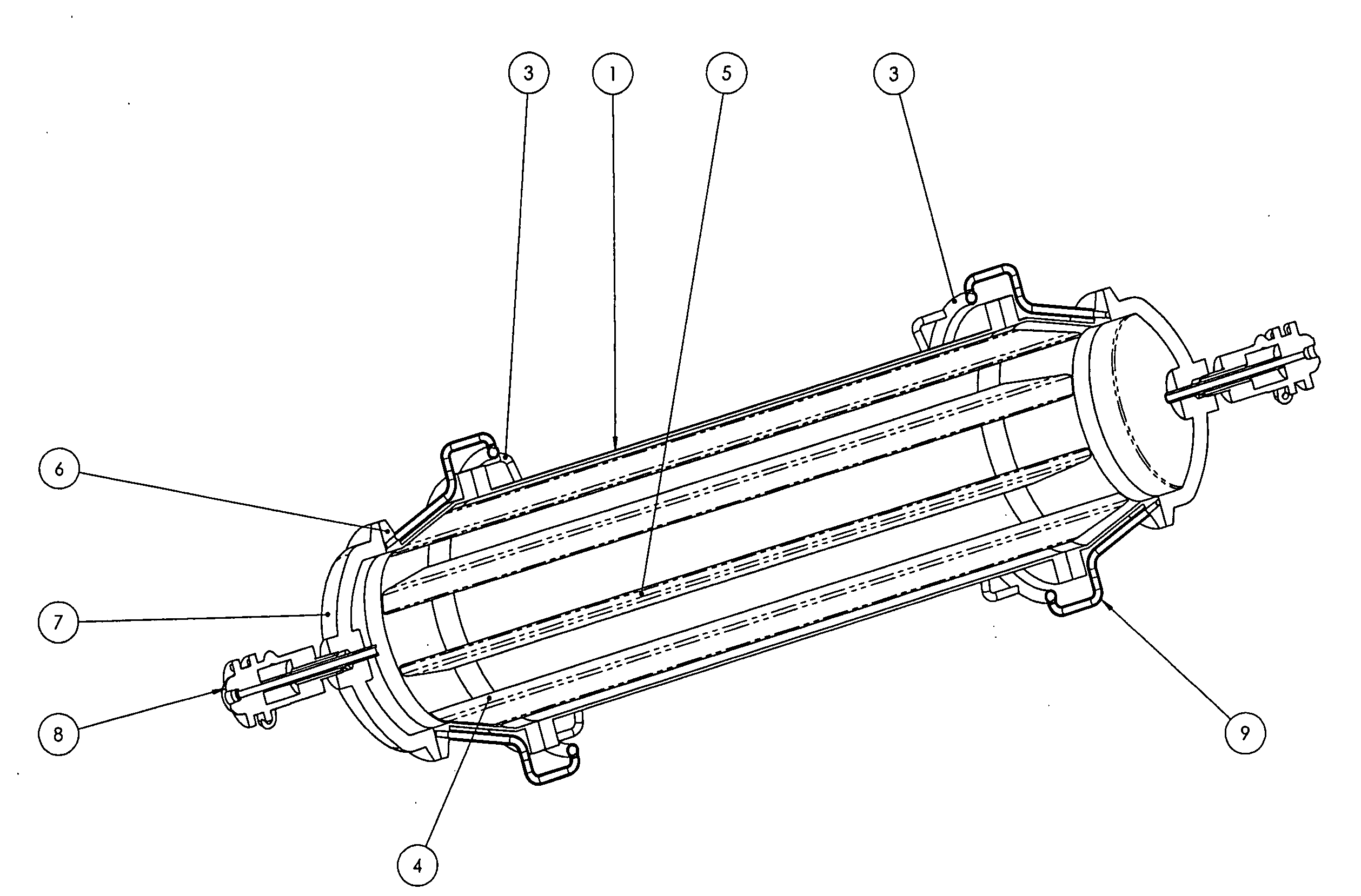
[0079]In one embodiment, steam may be introduced into, and water / steam may be exhausted through a common rotating union on each end of the autoclave. The end of the autoclave may be provided with one or more manifolds to distribute the steam and collect the spent waste steam to and from the tubes in the autoclave.

[0080]In the instance where autoclave operations require autoclave material to flow through the end of the autoclave, a manifolded door must be provided. The present invention provides one or more manifolded doors, to provide a sealed manifold against a system of tubes.

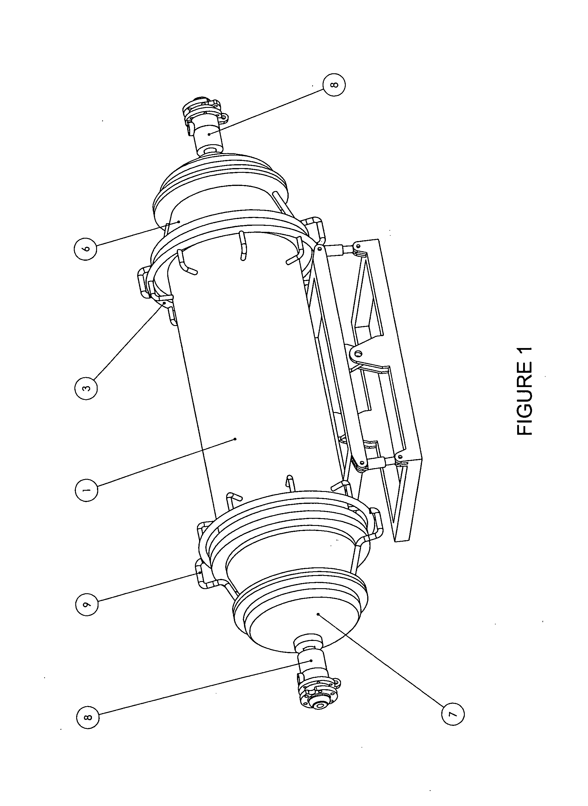
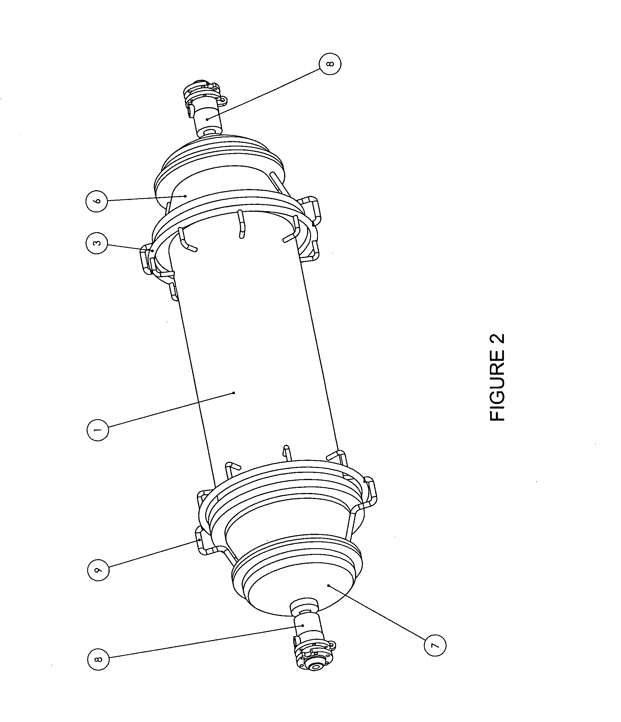
[0081]FIG. 1 is a perspective view of an autoclave apparatus for processing solid waste products, in accordance with one embodiment of the present invention. FIG. 1 provides a side perspective view of the autoclave 1, mounted on a ...


PUM

PropertyMeasurementUnit
pressureaaaaaaaaaa
pressureaaaaaaaaaa
temperaturesaaaaaaaaaa

Abstract

An autoclave system provides a means of sterilizing municipal solid waste, hydrolyzing many of its components, and preparing the material for post-autoclave automated separations. The present apparatus provides a means of drying the solid waste in the vessel, while conserving the energy used to dry the vessel. Non-contact steam is recovered through separations of steam and water, with condensate steam pressure regenerated by mechanical vapor recompression and condensate water returned to the boiler / steam generator. Heat transfer to combustion air, by heat transfer via heat pump to generate additional steam, and / or by mechanical vapor recompression recovers the latent heat of loose contact steam condensate. The process design provides for in-vessel drying while reducing the energy cost of operating a waste autoclave, as compared to the current art.

Description

TECHNICAL FIELD[0001]The present invention relates to the treatment of municipal solid waste and the like. This invention disclosure presents a means of utilizing steam to heat and dry wet heterogeneous solids inside a rotating autoclave with at least one entry and exit door.BACKGROUND OF THE INVENTION[0002]The present invention relates to systems and methods for treating process material and, more particularly, to systems and methods for treating municipal solid waste material, medical waste material, reclaimed paper and the like.[0003]This process typically involves sterilizing high density materials such as glass, plastics, metals and recovering others from municipal solid waste (MSW) and converting paper, cardboard, food waste, etc. to a usable fiber and separating it from other recyclable materials.[0004]As a result of increasing scarcity of landfills and more stringent environmental regulations, efforts have been made to reduce the volume of process material, such as municipal...

Claims


Application Information

Patent Timeline
Patent Type & Authority Applications(United States)
IPC IPC(8): A61L2/07A61L2/02A61L2/04
CPCA61L2/04B09B3/0091A61L2/07Y02W30/20B09B3/45
Inventor MICHALEK, JAN K.THOMAS, THEODORE J.
Owner ESTECH
Why Eureka
Try Eureka