
Regeneration control system

a technology of regeneration control and exhaust filter, which is applied in the direction of electrical control, machines/engines, mechanical equipment, etc., can solve the problems that the regeneration of the diesel particulate filter (dpf) cannot be efficiently regenerated, and the dpf will melt due to the problem of dpf, so as to achieve the effect of easy combustion

Active Publication Date: 2005-02-03
NISSAN MOTOR CO LTD
View PDF5 Cites 27 Cited by
  • Summary
  • Abstract
  • Description
  • Claims
  • Application Information

AI Technical Summary

Benefits of technology

[0009] The present invention was contrived in view of the above-described drawbacks, and an object thereof is to provide a regeneration control system for an exhaust filter that is capable of efficient DPF regeneration while preventing the diesel particulate filter (DPF) from melting due to rapid particulate combustion.

Problems solved by technology

It has been discovered that when the DPF regeneration control is performed in conditions (high temperature, lean air / fuel ratio) in which the particulates can be easily combusted, there is a possibility that the diesel particulate filter (DPF) will melt due to the rapid combustion of the particulates.
Another drawback is that regeneration of the diesel particulate filter (DPF) cannot be efficiently regenerated when the exhaust temperature is kept low and the exhaust air / fuel ratio is given a richer setting to prevent the particulates from combusting rapidly.

Method used


Image

  • Regeneration control system
  • Regeneration control system
  • Regeneration control system

Examples


Embodiment Construction

[0037] Selected embodiments of the present invention will now be explained with reference to the drawings. It will be apparent to those skilled in the art from this disclosure that the following descriptions of the embodiments of the present invention are provided for illustration only and not for the purpose of limiting the invention as defined by the appended claims and their equivalents.

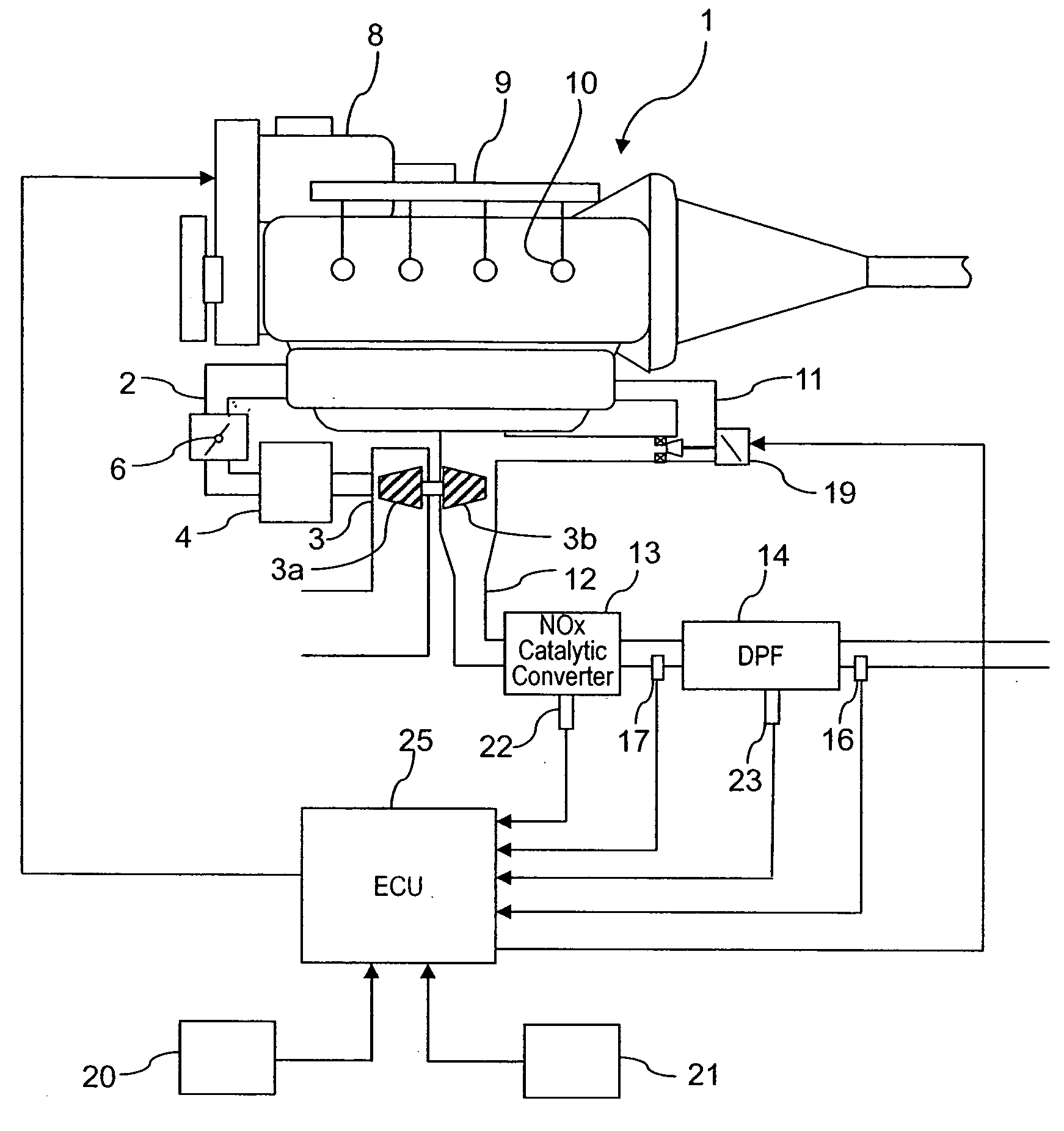
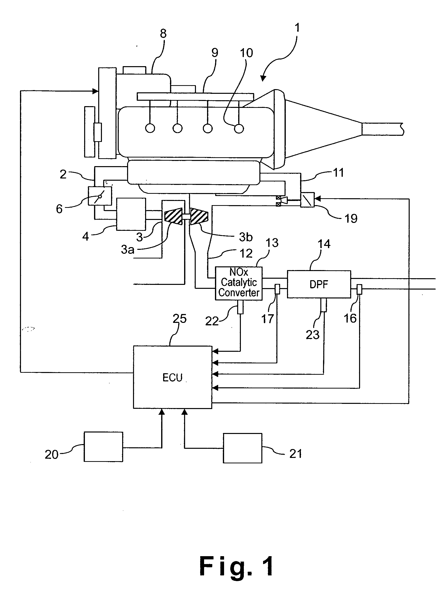
[0038] Referring initially to FIG. 1, a regeneration control system is illustrated for an internal combustion engine such as a supercharged diesel engine 1 in accordance with one embodiment of the present invention. The regeneration control system in accordance with the present invention can be applied to internal combustion engines used in automobiles and the like.

[0039] As shown in to FIG. 1, the engine 1 includes an air intake passage 2 having a turbocharger (supercharger) 3 with a compressor 3a disposed upstream in the air intake passage 2 of the air intake system. The compressor 3a serves t...


PUM


Abstract

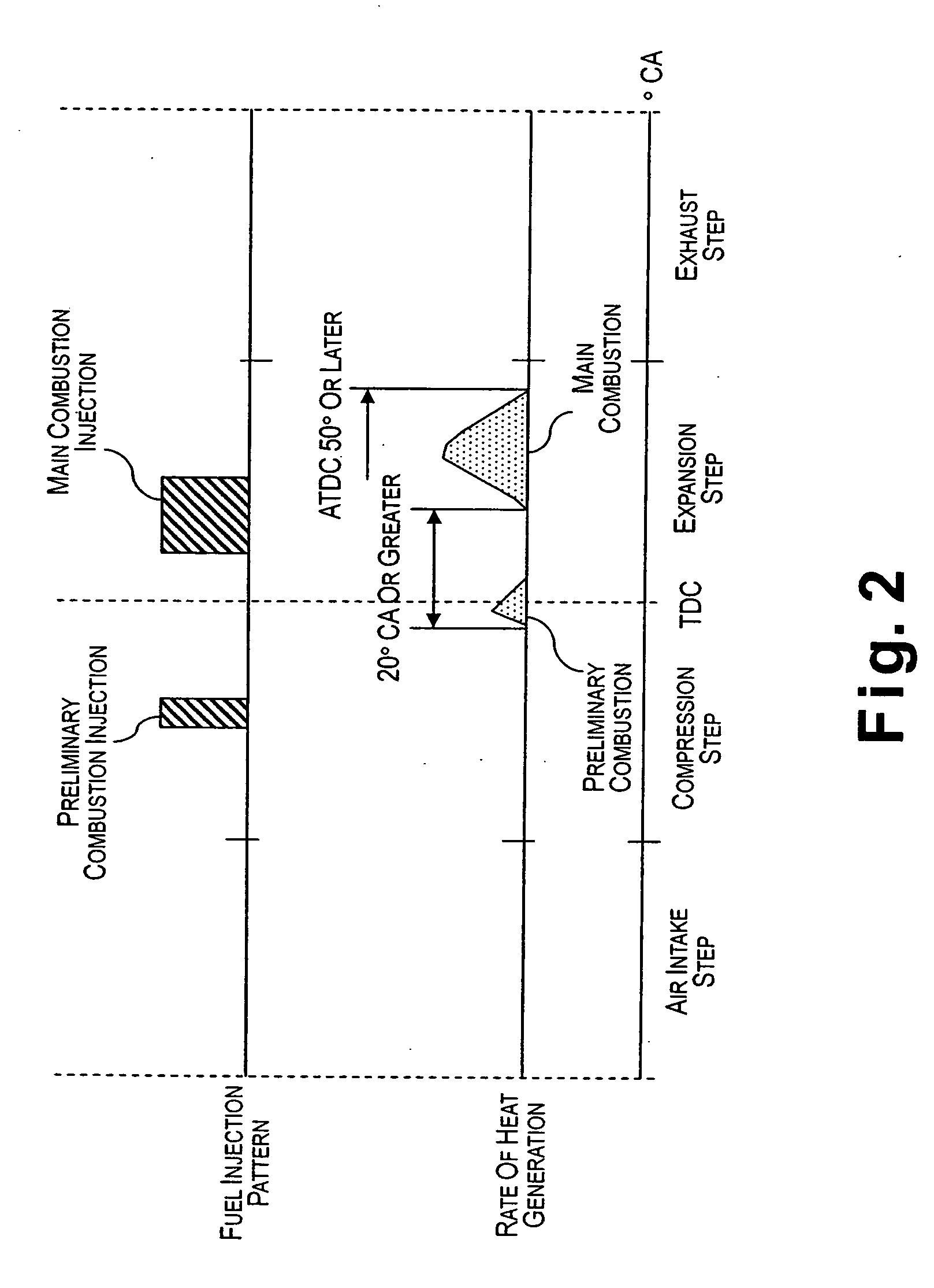
The regeneration control system is provided that conducts a regeneration processing for oxidizing particulate matter collected in the diesel particulate filter (DPF) whereby the regeneration processing can be performed efficiently while avoiding the melting of the diesel particulate filter. The regeneration control system is provided for an exhaust filter wherein at least one parameter selected from among the target filter temperature, target exhaust air-fuel ratio, and target regeneration control time in the DPF regeneration is varied in accordance with the amount of particulate matter when the exhaust air-fuel ratio and exhaust temperature are controlled to perform the DPF regeneration by staged retarded combustion, which is composed of preliminary combustion that is performed at least once in the vicinity of the top dead center, and main combustion that causes the generation of main torque and is initiated after the preliminary combustion has been completed.

Description

BACKGROUND OF THE INVENTION [0001] 1. Field of the Invention [0002] The present invention generally relates to a regeneration control system for an exhaust filter. More specifically, the present invention relates to a regeneration control system for oxidizing exhaust particulate matter collected by an exhaust filter. [0003] 2. Background Information [0004] In internal combustion engines such as diesel engines, an exhaust gas recirculating system (EGR system) is widely used wherein a part of the exhaust gas is recirculated to lower the combustion temperature in order to reduce discharge of nitrogen oxide (NOx). Some prior exhaust systems for diesel engines often include a diesel particulate filter (DPF) and a NOx trapping catalytic converter that are disposed in an exhaust passage. The diesel particulate filter (DPF) traps particulate matters (PM) in the exhaust gas, while the NOx trapping catalytic converter traps NOx in the exhaust gas when an air-fuel ratio in the exhaust gas is i...

Claims


Application Information

Patent Timeline
IPC IPC(8): F01N3/02F02M45/04F01N3/023F01N3/035F01N3/08F01N3/20F01N3/24F01N3/28F01N13/02F02D21/08F02D41/02F02D41/04F02D41/38F02D41/40F02D45/00F02M25/07F02M47/00
CPCF01N3/0821F01N3/0842F02D41/0057F02D41/029F02D41/401F02D41/402F01N13/009F02D2200/0812F02M25/0707F02M25/0788Y02T10/44Y02T10/47F02D41/403F02M26/05F02M26/66Y02T10/40
Inventor KITAHARA, YASUHISA
Owner NISSAN MOTOR CO LTD
Learn More