

Reactor for performing endothermic catalytic reactions
a catalytic reaction and endothermic technology, applied in the direction of physical/chemical process catalysts, gas-gas reaction processes, lighting and heating apparatus, etc., can solve the problem of suited to operation only at relatively low temperatures
- Summary
- Abstract
- Description
- Claims
- Application Information
AI Technical Summary
Problems solved by technology
Method used
Image

Examples
example 1
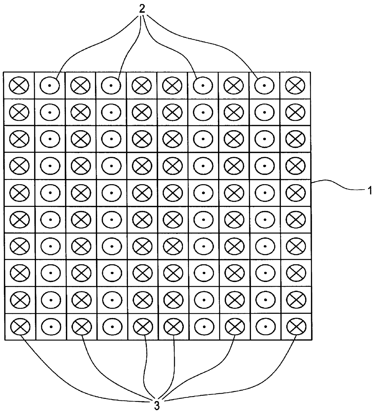
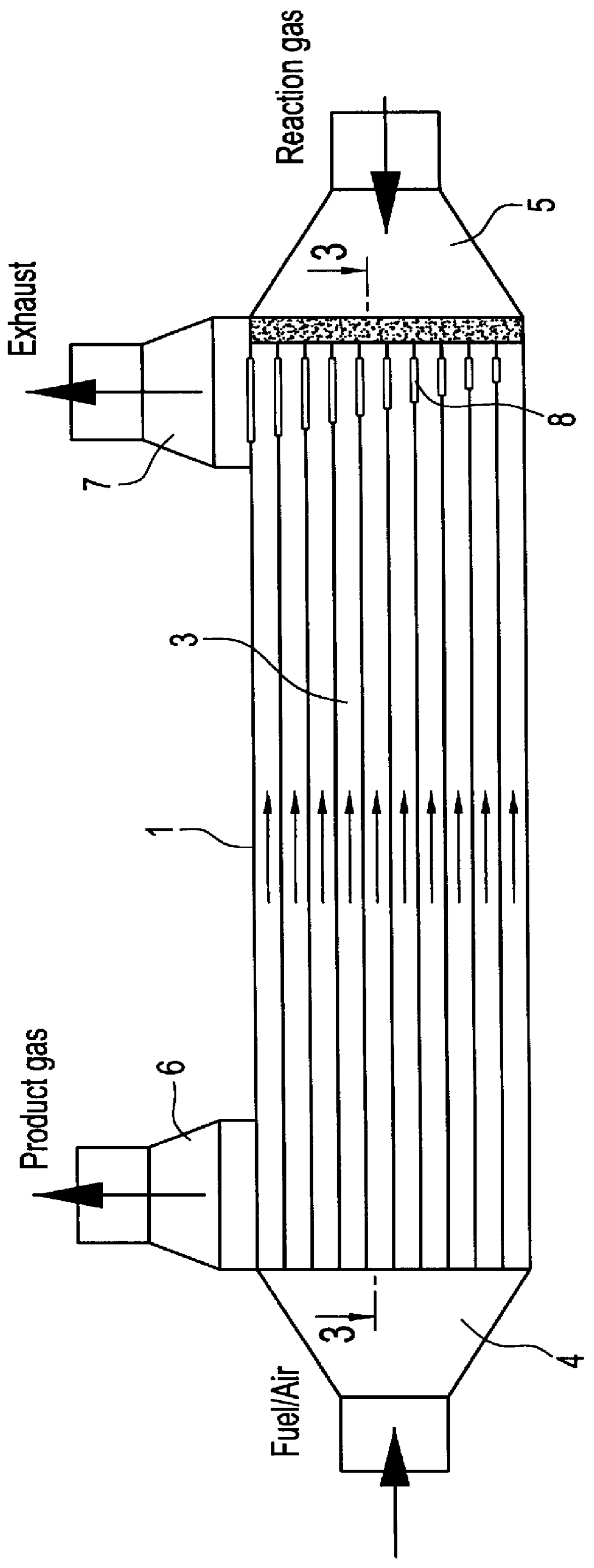
A gas-tight monolith with 15.5 cells per square centimeter made of .alpha.-aluminum oxide was used as a reactor for synthesizing hydrocyanic acid. The reactor had a length of 50 cm and a cross section of 2.6.times.2.6 cm with a total of 100 channels (10.times.10 matrix). The accessible orifice in the flow channels had dimensions of about 2.times.2 mm.sup.2. The thickness of the channel wall is about 0.55 mm. This monolith was subdivided into 60 heating and 40 reaction channels, for reasons of symmetry, as shown in FIG. 1. The volume of heating channels and reaction channels was together 0.2 l, of which 0.08 l represented the reaction channels. Heating and reaction channels were grouped together in rows. As shown in FIG. 1, the monolith 1 is made up of a plurality of layers of reaction channels 2, and a plurality of layers of heating channels 3. The symbol .times. represents fuel gas / air mixture flowing into the plane of the drawing and the symbol . represents reaction gas mixture fl...
example 2
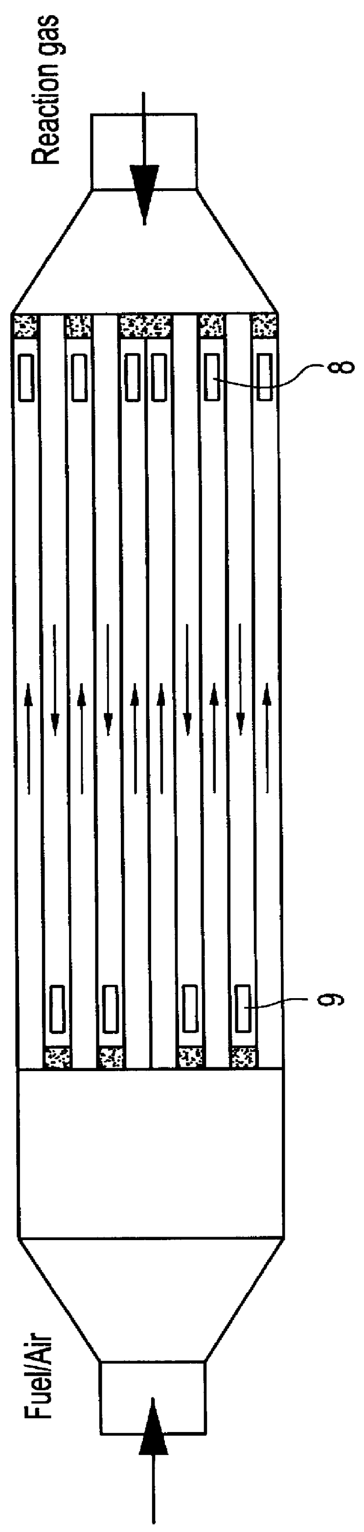
The reactor of Example 1 was modified according to the schematic representation in FIG. 4 with flame injector pipes. The latter were secured to an intermediate panel 10 in the gas injection stage 4 and extended into the heating channels to a depth of 20 cm. In this way, the combustion began first at the exit of the flame injection pipes at a depth of 20 cm in the interior reactor. FIG. 5 shows a sectional view through the reactor parallel to the plane AA of FIG. 4.
The purpose of this modification was to develop an even more steep temperature profile than in the previous example. In the heating channels, the same fuel gas / air mixture was burned as in example 1. For simplification of the measurement, the synthesis of the hydrocyanic acid was omitted. Therefore, only 110 l ammonia per hour were charged through the reaction channels. The measured temperature profile is shown in FIG. 7.
At the introduction point of the fuel gas / air mixture into the reactor, the temperature of 22.degree. C...
PUM
| Property | Measurement | Unit |
|---|---|---|
| temperatures | aaaaa | aaaaa |
| internal diameter | aaaaa | aaaaa |
| internal diameter | aaaaa | aaaaa |
Abstract
Description
Claims
Application Information