

Spray drying method and apparatus and cleaning method for such an apparatus
a technology of spray drying method and spray cleaning method, which is applied in the direction of spray drying method, drying, furnace type, etc., can solve the problems of fines to be returned, fines must be collected, and sometimes quite complicated ducting system, etc., to achieve less complicated and compact overall structure
Inactive Publication Date: 2000-05-09
NIRO
View PDF7 Cites 48 Cited by
- Summary
- Abstract
- Description
- Claims
- Application Information
AI Technical Summary
Benefits of technology
With this background, it is the object of the invention to provide a spray drying method involving the use of an integrated fluid bed and useful for production of agglomerated products of conventional or improved quality, which does not suffer from the above-mentioned disadvantages and provides important additional advantages with respect to a less complicated and more compact overall structure of the spray drying apparatus and in terms of facilitating cleaning of the apparatus, which is of significant importance when a spray drying apparatus is used for processing a range of different products requiring frequent cleaning and readjustment of the chamber.
By retaining the particles carried by the drying gas within the drying chamber itself the need for the complicated fines return systems involving the use of external cyclones or filters with associated pneumatic powder discharge and return transportation systems is completely eliminated.
It has further been demonstrated to be perfectly possible to design the integrated filters, which are preferably made with substantially rigid filtering walls of metallic, ceramic or polymeric materials or composites thereof, so that they will work well in the humid conditions prevailing in agglomeration dryers. The term "substantially rigid" is to be understood in the sense that the filtering walls could have a certain modest flexibility to provide for a better distribution of pressure forces.
Moreover, against a prevailing prejudice against exposing filters integrated in conventional drying chambers to a drying gas heavily loaded with particles, which are relatively moist and sticky, the invention has demonstrated that by appropriate arrangement and design of the filter elements and selection of process parameters such as the flow rate of the drying gas and the intermittent reverse gas cleaning pulses, blocking of the filters can be avoided to an extent making the method practical for continuous, contrary to batchwise, FSD dryer operation.
A significant advantage of the method and apparatus of the invention comes from the facilitated possibilities for cleaning-in-place of the integrated filters in the non-operative condition of the apparatus allowing for a reduction of the period of non-operation needed for such a cleaning.
As an important advantage the cleaning of the filter elements 11 may be performed concurrently with cleaning of the interior of the processing chamber by means not illustrated in the drawings in a single coherent process. Whereby the cleaning of the filter elements 11 from the inside may be assisted by a simultaneous washing of the external side of the filter elements 11.
Problems solved by technology
As disclosed therein as well as in EP-A-0 749769 conventional prior art suggestions for return of fines for use in an agglomeration process have suffered in general, however, from the disadvantage that the fines to be returned must be collected outside the chamber and transported to the chamber by a sometimes quite complicated ducting system.
Method used
View moreImage
Smart ImageViewing Examples

Examples
example 2
Fluidized spray drying of a dairy product was performed under the following drying conditions
The following product characteristics were obtained:
The primary particles produced were in the range from 20 to 60 .mu.m.
Login to View More PUM
| Property | Measurement | Unit |
|---|---|---|
| pulse pressure | aaaaa | aaaaa |
| particle size | aaaaa | aaaaa |
| flow rate | aaaaa | aaaaa |
Abstract
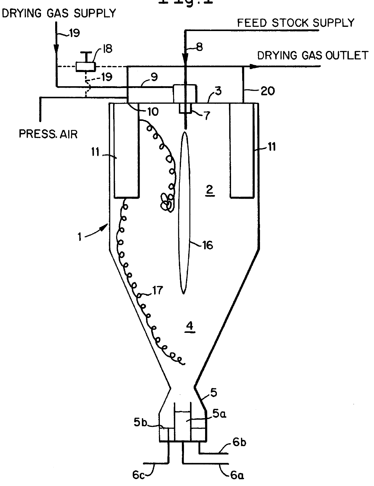
PCT No. PCT / DK97 / 00078 Sec. 371 Date Feb. 25, 1997 Sec. 102(e) Date Feb. 25, 1997 PCT Filed Feb. 20, 1997 PCT Pub. No. WO97 / 14288 PCT Pub. Date Apr. 24, 1997In fluidized spray drying of a feedstock to produce an agglomerate product by means of at least one spraying device (7) arranged in the upper part (2) of a vertically disposed drying chamber (1), in a lower part of which a fluid-bed is accommodated, a drying gas introduced into a processing zone (16) of the chamber (1) is exhausted through an integrated arrangement of filter elements (11) in the upper chamber part (2) to retain and allow agglomeration of the particles carried by the flow of drying gas on the filter elements (11). By intermittent supply of reverse flow gas pulses to the filter elements (11) the retained particles are released and returned to agglomeration zones (16, 17). The drying gas is introduced at a rate producing at the filter walls (13) a flow rate amounting to at least 150 cubic meters per hour per square meter of filter wall surface. In the non-operative condition of the spray drying apparatus the filter elements (11) may be cleaned-in-place by supplying a cleaning liquid to the interior of the elements.
Description
This invention relates to a method of spray drying a feedstock to produce an agglomerated product, comprising the steps of supplying said feedstock to at least one spraying device arranged in the upper part of a vertically disposed drying chamber, introducing a drying gas into a processing zone of the chamber outside said spraying device, forming a layer of fluidized particles in a lower region of the chamber and exhausting said drying gas from the chamber through outlet means disposed in said upper chamber part.Whereas the term "spray drying" refers, in general, to processes in which a fluid feedstock is at a relatively low temperature compared to the temperature of the drying gas, the feedstock may also be at a relatively high temperature with respect to the gas in processes which are sometimes referred to as "spray cooling". In the context of the present invention the generic term "spray drying" is used to encompass all such processes in which a fluid feedstock is sprayed into a ...
Claims
Login to View More Application Information
Patent Timeline
 Patent Type & AuthorityPatents(United States)
IPC IPC(8): B01J2/16B01D1/16B01D1/18
CPCB01J2/16B01D1/18
InventorBACH, POULMASTERS, KEITH
OwnerNIRO