Water saver fire hydrant

Inactive Publication Date: 2000-05-09
HONIGSBAUM RICHARD
View PDF8 Cites 65 Cited by
  • Summary
  • Abstract
  • Description
  • Claims
  • Application Information

AI Technical Summary

Problems solved by technology

Fire hydrants are installed in water systems to provide water at the pressures and flow rates needed for fire fighting, but when hydrants are opened illicitly, say for recreational purposes during the heat of summer, not only does the resulting flow flood streets, undermine infrastructure and put the lives of children at risk; it also reduces

Method used


Image

  • Water saver fire hydrant
  • Water saver fire hydrant
  • Water saver fire hydrant

Examples


Embodiment Construction

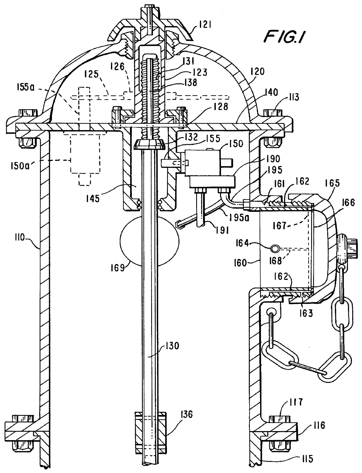
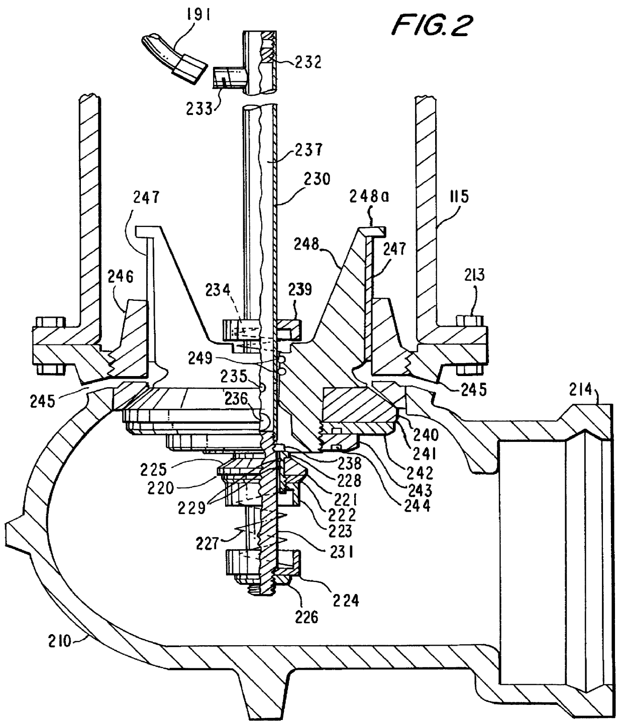
Turning now to the drawings, the embodiment of FIG. 1 is the upper barrel portion 110 and the bonnet portion 120 of a fire hydrant in accordance with this invention, the embodiment of FIG. 2 is the base portion 210 and the lower barrel portion 115 of that hydrant, and the embodiment of the combination of FIGS. 1 and 2 is a traffic-model compression-type dry barrel water saver fire hydrant The hydrant is connected to a water main by a hydrant lead that mates with flange 214.

Bonnet 120 and seal plate 140 are secured to upper barrel 110 with conventional bolts 113 and lower barrel 115 is secured to base 210 with conventional bolts 213, but upper barrel 110 is secured to lower barrel 115 with breakable bolts 117 and a breakable flange 116, and the breakable bolts and flange along with frangible stem coupling 136 make the hydrant a traffic model. While gaskets are normally installed between the parts mentioned (and elsewhere where appropriate), they have been omitted from the drawings to...


PUM


Abstract

Water saver fire hydrants save water by delivering their initial flow from a pilot valve to a collection of holes in the gasket faces of their hose and pumper outlet nozzles. These holes are normally closed off by the gaskets in caps and hoses, and the water that flows from those holes in the absence of those caps or hoses activates a mechanism inside the hydrant that either blocks attempts to obtain full flow from the hydrant or powers a hydraulic motor that closes the hydrant valves.

Description

1. Field of the InventionThis invention relates to fire hydrants and more particularly to fire hydrants that discourage unauthorized use.2. Description of the Related ArtFire hydrants are installed in water systems to provide water at the pressures and flow rates needed for fire fighting, but when hydrants are opened illicitly, say for recreational purposes during the heat of summer, not only does the resulting flow flood streets, undermine infrastructure and put the lives of children at risk; it also reduces pressures and flow rates to levels too low for effective fire fighting.Fire hydrants intended to discourage this unauthorized use are familiar from the patent literature, and examples include Barton, U.S. Pat. No. 5,520,210; Camp, U.S. Pat. No. 4,716,922; Etter et al., U.S. Pat. No. 5,622,202; Meneses, U.S. Pat. No. 5,588,460; Pollard, U.S. Pat. No. 5,469,724; Sigelakis, U.S. Pat. No. 5,549,133; Stehling et al., U.S. Pat. No. 5,596,893, and Sutton, U.S. Pat. No. 3,650,471.Barto...

Claims


Application Information

Patent Timeline
IPC IPC(8): E03B9/02E03B9/00F16K35/00F16K35/02
CPCF16K35/022E03B9/02Y10T137/0318Y10T137/5327Y10T137/86984
Inventor HONIGSBAUM, RICHARD
Owner HONIGSBAUM RICHARD
Why Eureka
Try Eureka