Making and using thermal spray masks carrying thermoset epoxy coating

a technology of thermoset epoxy and thermal spray mask, which is applied in the direction of coating, pretreatment surface, metal material coating process, etc., can solve the problems of unwanted coating adherently building up, unable to control the spray pattern to match all edges of the target, and losing the ability to deflect or shed particles

Inactive Publication Date: 2000-05-09
FORD GLOBAL TECH LLC
View PDF1 Cites 30 Cited by
  • Summary
  • Abstract
  • Description
  • Claims
  • Application Information

AI Technical Summary

Problems solved by technology

Although techniques are available to generally control and focus the spray as a conical pattern, such sprayed pattern cannot be controlled to match all edges of the target.
Once the masks become contaminated with some adhering particles, they begin to lose their ability to deflect or shed particles and an unwanted coating will adherently build up, similar to the coating on the target area.
As a group, such alternatives have proven to be deficient because either they are to expensive for use, or the protective coating is too viscous, absorbent, or porous to deflect the thermal spray particles, or the protective film roughens the mask surface to allow a build up of the spray coating on the mask.
Additionally, applicant has tried temporary films to protect the masking, such as use of shiny smooth aluminum fiberglass reinforced tape; such tapes have failed to provide durability and have had to be removed and replaced frequently.

Method used


Image

  • Making and using thermal spray masks carrying thermoset epoxy coating
  • Making and using thermal spray masks carrying thermoset epoxy coating
  • Making and using thermal spray masks carrying thermoset epoxy coating

Examples


Embodiment Construction

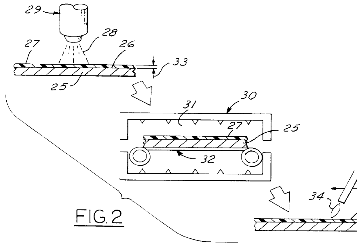
This invention has discovered that most thermally sprayed metal or ceramic materials (whether sprayed by oxy-flame, wire arc, or plasma torches) do not adhere or adhere poorly to thermoset epoxy material previously applied to masks. Surprisingly, the thermoset epoxy coating is not melted upon impact by the thermally sprayed metal or ceramic droplets. As a consequence, such coated masks eliminate the need for cleaning while providing a much longer service life. The absence of even lightly adhering metallic or ceramic particles to the coated masks eliminate the risk that such lightly adhering particles will peel off and contaminate the desired deposit of thermally sprayed particles.

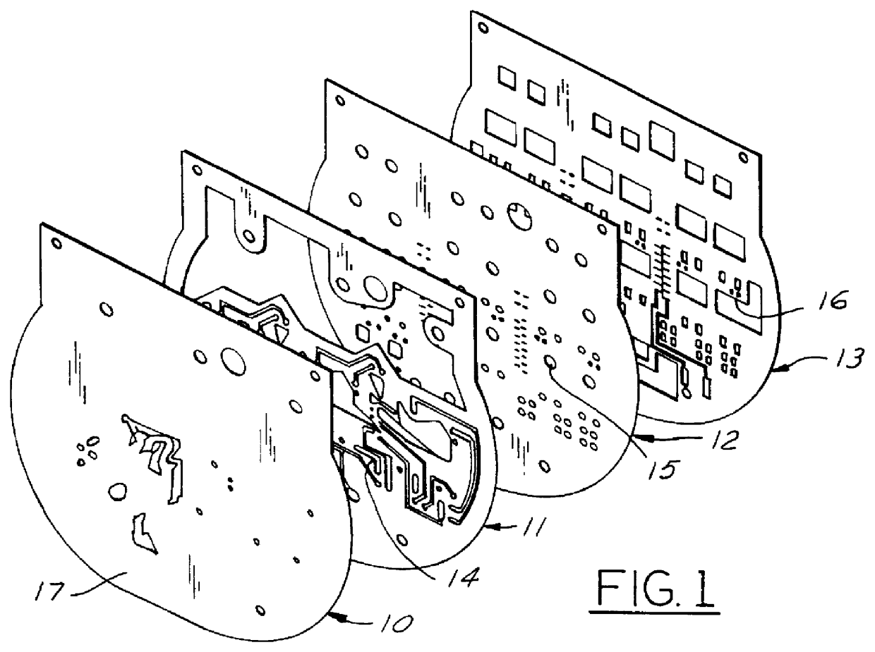
Masks are typically hard smooth covers that can come in many forms. FIG. 1 illustrates several different stainless masks 10, 11, 12, 13 that are used to define different micro circuitries for automotive electrical control components. Copper is sprayed through openings in the masks (such as indicated at 14, ...


PUM

PropertyMeasurementUnit
sizeaaaaaaaaaa
smoothnessaaaaaaaaaa
thicknessaaaaaaaaaa

Abstract

Method of making a mask assembly by providing a heat resistance mask substrate having an exposed surface with a surface smoothness less than 2000 micro inches, uniformly spraying a thermoset epoxy organic coating onto such exposed surface in one or more layers to provide a coating having (e.g., a thickness equal to or less than about 0.005 inches), a smoothness characterized by an average profilometer reading (Ra) of no greater than 1.5 micrometers, said coating being devoid of pores that exceed about 0003 inch in size, and flame polishing all or a portion of such coating to effect a surface finish of about 1.0 micrometers. A mask assembly which is useful in masking areas from thermal spray particles, comprising a heat resistance substrate presenting an exposed grit blasted surface having a smoothness of less than 2000, and a thin thermoset epoxy coating bonded to said exposed surface and having a surface smoothness characterized by an average profilometer reading (Ra) no greater than 1.5.

Description

This invention relates to the technology of thermal spraying metals or ceramics, and, more particularly, to the technology of providing a low cost, flexible, self-leveling, non peelable, self-adhering coating on masks that will deflect thermally sprayed particles and prevent adherence to the mask.DISCUSSION OF THE PRIOR ARTThermal spraying techniques will deposit very hot viscous particles (greater than 700.degree. C.) onto a target surface usually 3-12 inches away from the spray gun nozzle. Although techniques are available to generally control and focus the spray as a conical pattern, such sprayed pattern cannot be controlled to match all edges of the target. Accordingly, there must be a certain degree of overlap beyond the precise target edges to obtain the proper coating thickness, area definition, and physical characteristics. Accordingly, masks are used to cover surfaces adjacent to the intended coated edges to prevent adherence. Masks are usually metallic, such as polished st...

Claims


Application Information

Patent Timeline
Patent Type & Authority Patents(United States)
IPC IPC(8): C23C4/00B05B15/04
CPCC23C4/005B05B16/60C23C4/01
Inventor PERGANDE, PAUL EARLKINANE, JEFFREY ALANPANK, DEBORAH ROSECOLLINS, DAVID ROBERT
Owner FORD GLOBAL TECH LLC
Why Eureka
Try Eureka